Welcome to Our Community

Some features disabled for guests. Register Today.

KRE CO2 2x4 Laser

Discussion in 'Laser Cutters' started by Kevon Ritter, Sep 6, 2020.
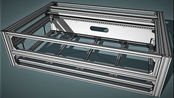
  1. Jaem Espinoza

    Builder

    Joined:
    Feb 24, 2019
    Messages:
    2
    Likes Received:
    0
    Good afternoon, congratulations on your compilation, I like it very much, greetings from Ecuador, I am aware of all your publications, when I have the frame, I would like to see photographs of it, and if possible, a list of parts of the aluminum profiles with measurements, I would like to start building your compilation with my students.
     
  2. Kevon Ritter

    Kevon Ritter Veteran
    Builder

    Joined:
    Apr 30, 2015
    Messages:
    597
    Likes Received:
    293
    Having the dimensionally critical parts in hand makes a heck of a difference. I was able to model the head, and confirm the mirror mounts and laser path. I had to push the gantry mirror forward by 15mm. Plus I have to factor in the adjustment knobs sticking out another 12mm from the mirror. I would prefer to maintain travel, so I'll have to extend the Y depth of the frame by 10mm. Any more clearance issues and I'd rather put the extrusion on the mill and notch out the area that needs it.

    I did miss out on the laser tube. I was going for a 60W for $140, but it's no longer available. Finding anything below $250 is a struggle. I'll just drop down to a 50W if nothing pops up by the time I'm ready in a couple of weeks. It can hold up to an 80W.
     

    Attached Files:

  3. Kevon Ritter

    Kevon Ritter Veteran
    Builder

    Joined:
    Apr 30, 2015
    Messages:
    597
    Likes Received:
    293
    Before and after 10mm extension.

    KRE CO2 V5 Assembly 66.png KRE CO2 V5 Assembly 67.png


    Control panel size comparison

    KRE CO2 V5 Assembly 68.png


    These two shots are with the bed at max height. The most I can "sink" the tube would be the first pic. What's stopping anyone from cutting the tube to make the laser head more compact? The important part is the lens which wouldn't be affected. Although the Z travel is 110mm, the effective height with the head unmodified should be about 80mm.

    KRE CO2 V5 Assembly 69.png KRE CO2 V5 Assembly 70.png
     
  4. KokomoJoe

    KokomoJoe New
    Builder

    Joined:
    Jan 5, 2014
    Messages:
    2
    Likes Received:
    0
    Good looking build. I have a question about your idler pulley bracket and pillow blocks used on the drive shaft, are those 3d printed? If so how are they working?

    The pillow blocks with bearings should be just fine as I don't think there would be a large radial load on the shaft.
     
  5. Kevon Ritter

    Kevon Ritter Veteran
    Builder

    Joined:
    Apr 30, 2015
    Messages:
    597
    Likes Received:
    293
    There is a printed spacer between two aluminum plates. I plan to print all of the plates initially, then switch over once I know everything is working. I actually just started printing parts today.

    I'm much further behind than I had hoped. I still have a pile of parts sitting there waiting for the extrusion itself.
     
  6. Kevon Ritter

    Kevon Ritter Veteran
    Builder

    Joined:
    Apr 30, 2015
    Messages:
    597
    Likes Received:
    293
    Quick update: I really don't have much to show as of now. Things didn't quite go as intended (again), but the project is still moving along. I have been slowly refining the design little by little.

    1) I completely removed the rear fume evacuation. From the beginning, I knew it was only a temporary solution. The ideal solution would be a down draft table. I did shop around for possible parts.

    2) A few minor tweaks have been made to some extrusion lengths. I did shy away from the idea of as few unique lengths as possible. If it's all being professionally cut to length, it really doesn't change anything.

    3) I have already begun printed most of the supporting components.

    4) I'm still not 100% sure on the X axis cable carrier. I got the "10mm x 10mm" stuff, but it wants to remain curved instead of straightening out. Over a shot distance, this wouldn't be an issue, but over a meter is. I'll see if I can print something. It's really only needed for the air line and a small 5v power cable for the laser.
     
  7. Kevon Ritter

    Kevon Ritter Veteran
    Builder

    Joined:
    Apr 30, 2015
    Messages:
    597
    Likes Received:
    293
    The airflow has been completely revised. There are 120mm fans on either side blowing in. This still may not be enough for the radiator, so there is an open portion just below it. I dropped the top edge down by 20mm (yellow line) to allow air to flow over the top. This plus the 5mm gap around the entire border (excluding the rear) of the canopy/hatch/door/lid/whatever should provide a bit of air while still keeping it under a large amount of negative pressure. As for extraction, a 6" fans are priced the same as the smaller 4" fans, and are rated at 400+CFM.
    KRE CO2 V5 Assembly 71 airflow.png

    Then came the revised power supply mounting. The reason for them being flat and stacked before was space concerns. With the fume extraction being revised, that's no longer an issue. In these pics, the air pump would be hanging above the laser PSU, but it can fit behind/under the system PSU stack.
    KRE CO2 V5 Assembly 72.png KRE CO2 V5 Assembly 73.png KRE CO2 V5 Assembly 74.png

    As I'm sitting here unable to physically work on it, I look and slowly find things that can be improved. Most of the mods have been related to user friendliness as well as slight appearance mods just to satisfy even the most persistent CDO. It's no longer as 'space optimized' as it was before, but it is insanely serviceable. Everything can be accessed without moving anything.
     

    Attached Files:

  8. Kevon Ritter

    Kevon Ritter Veteran
    Builder

    Joined:
    Apr 30, 2015
    Messages:
    597
    Likes Received:
    293
    Lots of limit mount tweaking. I also printed a small section of 3060 (exact product of course) to test fit. The screw adjusted trigger is for the hatch, but I use a similar idea for the bed limit.

    My printed t-nuts as well as the regular 2020 but (when turned wide) fit well.
     

    Attached Files:

    REdington likes this.
  9. REdington

    REdington Well-Known
    Builder

    Joined:
    Jan 24, 2015
    Messages:
    98
    Likes Received:
    43
    I like it. Gives me more Ideas for when I get that far.
     
    Kevon Ritter likes this.
  10. Kevon Ritter

    Kevon Ritter Veteran
    Builder

    Joined:
    Apr 30, 2015
    Messages:
    597
    Likes Received:
    293
    This caught me off guard. Among the pile of parts I have waiting were the front panel illuminated rocker switches. I honestly didn't look into their details aside from size and color. I decided to take a look at them just for fun. That's when I saw that they were 125VAC. I didn't realize that there were different voltages for the internal light, so I went to see if they would work on 12V. Of course, the result was nothing. Then I hooked it up to an AC outlet, and boy was I greeted by the ugliest most pathetic light ever. It uses a tiny 120V rated filament bulb, but the filament bulb is a crazy warm white. I would actually say it's closer to a car's turn signal amber.

    I pulled out my stash of SMD LED's and got to work. I have pretty much every size between 0603 and 5050. After taking the rocker switch apart, I found that four 3528's fit perfectly when soldered back to back. You can see the result below. I would it's too bright, but this isn't an issue as I can always just add an external resistor on the terminal with ease. The major win comes from the fact that the entire switch is now illuminated, and not just a tiny spot.

    This is a completely random and seemingly unnecessary update, but it's the little details that matter in my book. Now that I know how illuminated rocker switches work, I'll be retrofitting the rest.

    EDIT:
    Made three new switches, for a total of three new switches and one that I experimented to heck and back on. :ROFL:
     

    Attached Files:

    #40 Kevon Ritter, Mar 4, 2021
    Last edited: Mar 4, 2021
  11. REdington

    REdington Well-Known
    Builder

    Joined:
    Jan 24, 2015
    Messages:
    98
    Likes Received:
    43
    @Kevon Ritter
    What size is your "Y" axis shaft??? I can't decide between 1/4" and 3/8" for mine. With 1/4", I think I'll get some whipping, and the 3/8" will have more inertia, but more stable. My motor will be centered between the 2 rails.
     
  12. Kevon Ritter

    Kevon Ritter Veteran
    Builder

    Joined:
    Apr 30, 2015
    Messages:
    597
    Likes Received:
    293
    I'm using 8mm powered by a 269oz Nema 23 with a 1:2 reduction. I haven't exactly out it to the test yet though.
     
    REdington likes this.
  13. REdington

    REdington Well-Known
    Builder

    Joined:
    Jan 24, 2015
    Messages:
    98
    Likes Received:
    43
    Thanks
    269oz is a lot. With that you could do a 2 to 1 speed up (instead of reduction) and have a lot of speed and I think you could retain accuracy.
    X and Y on mine will be 78oz 17's. Z will the same but with a 2 to 1 reduction.
     
  14. Kevon Ritter

    Kevon Ritter Veteran
    Builder

    Joined:
    Apr 30, 2015
    Messages:
    597
    Likes Received:
    293
    I got 566oz for my mill so the 269oz were hand me downs. :D One is also being used on Z.

    I do have one concern though: power. From the start, I wanted everything to be controlled through the machine itself. This meant having an onboard outlet to power the air pump as well. Now that I ditched the "entry level" fume extractor for something beefier, there is now an extra 130W load. I'm considering adding a second socket for the air pump and extractor. I need to sit down and create a wiring diagram to better explain.


    AC Socket 1 > 25A SSR > CO2 PSU, 24V PSU, and 12V PSU
    > 5V PSU (E-Stop, Extractor Relay, and Diode Laser)

    AC Socket 2 > Air Pump 10A SSR and Extractor 10A SSR

    The air pump relay would be triggered by the controller. The extractor relay would be triggered by a front panel switch which gets power from the 5V PSU hooked up to Socket 1. That 5V PSU will always be on once the socket has power.

    I'm going to go look at other builds and see what I can piece together. It is rated at 15A, but I just don't have confidence in the medium size spade connector.
     

    Attached Files:

    REdington likes this.
  15. JustinTime

    JustinTime Veteran
    Builder

    Joined:
    Dec 18, 2013
    Messages:
    758
    Likes Received:
    253
    How did you get the 4 LED in a series to work on 120V AC or do they work on 12V DC?
     
  16. Rob Taylor

    Rob Taylor Master
    Builder

    Joined:
    Dec 15, 2013
    Messages:
    1,470
    Likes Received:
    746
    If their forward voltage drop is say, 2.2V each at say, 30mA, that would be 8.8V just across the diodes themselves. On 12V you'd have 3.2V left to go across a resistor, and if you were trying to current-limit to 30mA, 3.2/0.03 = 107 ohms, so a 100R external resistor would work.

    You can basically run LEDs on anything, as long as you account for their voltage drop and current limitations. If you had enough in a row in series you could plug each end right into the wall outlet.
     
  17. Kevon Ritter

    Kevon Ritter Veteran
    Builder

    Joined:
    Apr 30, 2015
    Messages:
    597
    Likes Received:
    293
    Orange/Amber and Red operate at 1.8-2.6V. Every other color operates a 3.0-3.2V. These are just hooked up to 12V, which are perfect for the four 3.0-3.2V Blue diodes in series. One thing to keep in mind is that size does not matter. Unless you go with a diode that clearly operates out of the normal range (2V or 3V at 20mA), they are all the same. If I choose to dim them, I can add an external resistor on their ground pin.
     
  18. Rob Taylor

    Rob Taylor Master
    Builder

    Joined:
    Dec 15, 2013
    Messages:
    1,470
    Likes Received:
    746
    I've seen blue at ~2.2-2.6 and red at 1.6, so as with most things, that's probably not an absolute. You'd think the actual solid state physics would be pretty fixed, but I've found it pays to check the datasheet just in case.
     
  19. Kevon Ritter

    Kevon Ritter Veteran
    Builder

    Joined:
    Apr 30, 2015
    Messages:
    597
    Likes Received:
    293
    Slowly getting a full idea. There is still quite a few connections to make. I also have to add the water protection switch.
     

    Attached Files:

  20. Kevon Ritter

    Kevon Ritter Veteran
    Builder

    Joined:
    Apr 30, 2015
    Messages:
    597
    Likes Received:
    293
    I ran out of time, but here is what I have so far. I had the brilliant idea to use the onboard 12V to trigger the main system 25A SSR. The E-Stop would kill power to the entire machine through that SSR. Now I say brilliant after realizing that the machine wouldn't have power to tell the SSR to power up the machine. :ROFL: And something tells me that there wouldn't be enough of a trickle/leakage current to trigger the SSR into a closed position after a power down.

    With that said, I still need a tiny power source.
     

    Attached Files:

  21. REdington

    REdington Well-Known
    Builder

    Joined:
    Jan 24, 2015
    Messages:
    98
    Likes Received:
    43
    You could have a separate 12V power that is live all the time (with it plugged in of coarse) to trigger the SSR's. I like the idea of only having 12V at the Estop to save the contacts.
     
  22. Kevon Ritter

    Kevon Ritter Veteran
    Builder

    Joined:
    Apr 30, 2015
    Messages:
    597
    Likes Received:
    293
    The only connections I don't have on here are the USB/serial/ethernet wires for communication between the controller and the interface. I added relay control to the water pump and cooling fans just for the sake of having it in the drawing.
     

    Attached Files:

  23. Kevon Ritter

    Kevon Ritter Veteran
    Builder

    Joined:
    Apr 30, 2015
    Messages:
    597
    Likes Received:
    293
    I'm opting for new sockets that will let me use right angle power cords. They also have full size terminals that I would have to wire instead of the tiny little pin contact. Of course they are blue.

    The relays would be behind the PSU's. They'll have enough room to add a heat sink if necessary.
     

    Attached Files:

    REdington likes this.
  24. REdington

    REdington Well-Known
    Builder

    Joined:
    Jan 24, 2015
    Messages:
    98
    Likes Received:
    43
    I might of missed it, but looking over your wiring, I see no EMI filter. Are you going to one??
     
  25. Kevon Ritter

    Kevon Ritter Veteran
    Builder

    Joined:
    Apr 30, 2015
    Messages:
    597
    Likes Received:
    293
    I thought about it, but wasn't planning on using one. Any decent quality power supply has filters built in. The only time I've really seen EMI filters mentioned are from those hunting down issues. Those issues often remain even after the implementation of a filter. I'm not an electrician, but I do follow a few basic rules.
    1. Do not run Power and Signal wires in close proximity. Anything over 5V gets separated.
    2. Properly ground everything to a single ground point. (star pattern)
    3. Shield any wire that has the potential to be EMI sensitive. (every Signal wire)
    4. Shield any wire, in close proximity to signal wires, that has the to produce EMI. (Stepper wires)
    5. Run everything in pairs.
     
    Peter Van Der Walt and REdington like this.
  26. Kevon Ritter

    Kevon Ritter Veteran
    Builder

    Joined:
    Apr 30, 2015
    Messages:
    597
    Likes Received:
    293
    I found another area for improvement. The Sketchup pictures aren't the final model, but it works as a comparison between new and old. The old mount would have to be wedged for height adjustment. The new has screws underneath that push the "magazine" upwards. The magazine is then clamped into the "lower receiver" for a secure fit. My FBI agent probably thought I was trying to design my own AR.

    I also wouldn't mind adding another reservoir.

    Finally the update anyone cares about:
    The shipping info was glitching so I had to contact customer service to straighten that out. Then the extrusion will be on it's way!
     

    Attached Files:

  27. Kevon Ritter

    Kevon Ritter Veteran
    Builder

    Joined:
    Apr 30, 2015
    Messages:
    597
    Likes Received:
    293
    Well that hurt like heck. I've been putting it off for too long, but the extrusion is on order. It probably would have been 30% cheaper to go the 2020/2060 route, but I had my design objectives.

    There are only three electronic components left. The CO2 PSU is no issue, but the stock on tubes comes for a second, then goes for a month. Then there is the controller, which I'm still 10% on the fence on.

    I made a few updates to the bed. I was debating between using rods or strips/bars. Rods would be a little stronger. Strips would have a lower cross section. Seeing @REdington made the decision clear. Now the next consideration is bed height/ The machine was designed around a convenient 24"x48", which means that I can use 24" strips and slightly raise them inside the frame. This would allow the honeycomb to be even with the top. The concern here is that the bed support blocks would be exposed to the laser. The second option is to use longer strips and mount them flush to the bottom of the frame. This would recess the bed by 5mm. This isn't a bad thing as it adds a border and gets the plastic parts out of the laser's path. However, I would need an awkward 26.5" length.
     

    Attached Files:

  28. Peter Van Der Walt

    Peter Van Der Walt OpenBuilds Team
    Staff Member Moderator Builder Resident Builder

    Joined:
    Mar 1, 2017
    Messages:
    13,986
    Likes Received:
    4,105
    Get it when you absolutely need it. They have a "shelf life" and depending on how long at sat at the factory, on a boat, at customs, and at the dealer, you might only have a month or two left. I have made that mistake before, by the time I had the frame built and calibrated i had two dead tubes sitting on the shelf
     
  29. REdington

    REdington Well-Known
    Builder

    Joined:
    Jan 24, 2015
    Messages:
    98
    Likes Received:
    43
    Mine are .750" wide X .062" thick flat bar stock.
    Try to get it locally and see if they will cut to length or get a long piece and cut it on a miter saw.
     
  30. Kevon Ritter

    Kevon Ritter Veteran
    Builder

    Joined:
    Apr 30, 2015
    Messages:
    597
    Likes Received:
    293
    I've noticed that all "20" sellers happen to be the same person with only a single tube as when one sells, they all go out of stock together. Now that you bring that up, it wouldn't hurt to ask the seller what the manufacturing date is before purchase. I've already accepted that as a negative to purchasing a cheaper tube. Once I figure things out, I'd be able to justify something much nicer. Considering what I want to cut, I might honestly have more than enough power with even a weakened tube.

    I planned on using .125" x .5". Local options suck when you're on an island. I've had to ship everything to a buddy in GA. I would either grab the stuff when I'm there, or have him ship everything bulk. Large items like the extrusion, and even material that I plan to cut, has to be sent to a port in south Florida for shipment. That's a long way of saying that there is only a very limited Home Depot here.
     

Share This Page

  1. This site uses cookies to help personalise content, tailor your experience and to keep you logged in if you register.
    By continuing to use this site, you are consenting to our use of cookies.
    Dismiss Notice