Welcome to Our Community

Some features disabled for guests. Register Today.

INDY-TR12 CNC

Discussion in 'CNC Mills/Routers' started by David Bourne, May 27, 2019.
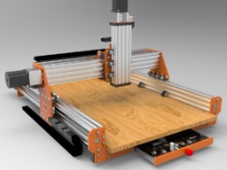
  1. David Bourne

    Builder

    Joined:
    Aug 11, 2016
    Messages:
    25
    Likes Received:
    36
    David Bourne published a new build:

    Read more about this build...
     
  2. matt_o_70

    matt_o_70 New
    Builder

    Joined:
    Dec 15, 2013
    Messages:
    54
    Likes Received:
    15
    Hi David,
    I Love it, easy to see you have put much time and work into this! Very beautiful work.

    Reminds me a bit like my other favorite inspiration CNC project - Platform CNC.
     
  3. Tracy Ranson

    Tracy Ranson Well-Known
    Builder

    Joined:
    Nov 4, 2014
    Messages:
    88
    Likes Received:
    32
    Awesome looking machine...Would you mind sharing some more information such as hardware supplier(s) you used to source parts like v wheels, concentric bushings, eccentric bushings, shouldered bolts etc. If you would also like to toss in a few DXF files of your plates that would be totally acceptable.
     
  4. David Bourne

    Builder

    Joined:
    Aug 11, 2016
    Messages:
    25
    Likes Received:
    36
    Thanks, and yes I did put a lot of work in, it's not completely finished yet but it's almost there. WOW.. I had not seen the platform CNC, that is a great kit!
     
  5. David Bourne

    Builder

    Joined:
    Aug 11, 2016
    Messages:
    25
    Likes Received:
    36
    Hi,

    Many thanks for the comments. The kit is not complete yet, I am still tweaking the design, but I expect to have some parts ready to build the first model in about 2 to 3 weeks. I am very busy at work at the moment so don't have a lot of spare time.
     
  6. Andreas Bockert

    Andreas Bockert Well-Known
    Builder

    Joined:
    Oct 1, 2017
    Messages:
    142
    Likes Received:
    78
    Hi

    Looks great and I like your thinking.

    I would suggest not blocking of the ends of the machine (I.e. with the electronics case and the front fence) since it’s very useful to allow the workpiece to extend outside the machine.

    I remember seeing a build that had the electronics under the machine. The control box has the same footprint as the machine.

    Anyway, looks good and keep us posted.
     
  7. David Bourne

    Builder

    Joined:
    Aug 11, 2016
    Messages:
    25
    Likes Received:
    36
    Thanks for the comments, they are really appreciated. I am going to change the front plate so that the work base can extend beyond the front plate, that makes sense. But the back plate will not allow any further movement so that is staying as it is, and I like the electronics on the back, almost all the wiring is hidden with this as it would be if the electronics were under the kit, but I figure easy access is needed in case anything needs changing so I am keeping that, plus I think it looks good. I am almost there now and i will be putting revised pictures up soon with explanations of why i have made the design the way it is.
     
  8. Andreas Bockert

    Andreas Bockert Well-Known
    Builder

    Joined:
    Oct 1, 2017
    Messages:
    142
    Likes Received:
    78
    Looks nice! I like the bit drawer. You'll probably want a second mount for the router in order to distribute the cutting forces over a larger part of the Z axis.

    That drawing shows some serious (I assume) F360 skills!
     
  9. David Bourne

    Builder

    Joined:
    Aug 11, 2016
    Messages:
    25
    Likes Received:
    36
    Another mount option is a good idea but I will look at that later when I decide which spindle type to use. The skills are for Alibre Design & Keyshot, I can use F360 but prefer Alibre, that may change though. Thanks for the comments.
     
  10. David Bourne

    Builder

    Joined:
    Aug 11, 2016
    Messages:
    25
    Likes Received:
    36
    Here are some real world pictures of parts that are arriving. This is the lead screw evolution, from right to left, the first is the standard 8mm as used in many builds. I think (my opinion) for small machines up to 600mm these are probably suitable but for any longer actuator then a larger screw size should be used.

    Then for the 2nd from right evolution stage I looked at TR12x3 and 12mm non-machined ends that fit outside the plate, not inside, these will work and can be used on some builds but I deciced that although these were good they are not anti-backlash so I decided not to use these so I have these spare in my work space.

    010.JPG

    3rd from right: Then I found the correct suppliers for the housing and for the anti-backlash nut, this will of course support machined and non-machined TR12 screws so 3rd from right is the absolute best solution for C-Beam and TR12 screws. I am so pleased to have found this combined set of suppliers, the nut has a much greater hold area than the 8mm and is machined precisely to fit into the housing, and as a bonus it is anti-backlash, perfect!

    013.JPG

    Above you can see that the housing fits beautifully inside the C-Beam.

    The housing costs more than a normal item of this type but it so massively improves possibilities for the cnc kit it is worth the extra cost.

    Finally, 4th from right on the main picture a TR16x3 nut and housing. I will use this on my larger format machines and of course the nut does not fit into the C-Beam inner shape but on 1.5M or larger C-Beam lengths such as a 3Mx1.5M machine the nut placement is OK on the outside.
    010.JPG pic1.jpg


    Last, here is a set of plates that I ordered for the first INDY-TR12 concept build, these were not even delivered when I realized I wanted to change the build to accommodate a bit drawer and make some other changes so these plates are spare for the moment.

    As you can see the plates as supplied are not cleaned or brushed like the beautiful brushed black OB plates but when you order one set lie I have then it is not cost effective to order them machined like the OB plates.

    It is not hard to clean these and they are exact shapes and from certified 6mm thick AW 5754 aluminium.
    004.JPG

    I found out through trial and error that many laser cutter parts service companies use softer non-certified aluminium which is a poor quality alloy mix and not hard enough for CNC work so again I took some time to find the correct supplier who would guarantee certificated materials, this was www.fractory.com. The total cost for this plate set was £130.00.

    These plates fit this early design
    beta2.jpg beta3.jpg beta1.jpg beta4.jpg


    The design has evolved a great deal since this early stage but I am nearly complete. Once again I decided to change the design because I wanted to use the dead space that is always present in this kind of design so I adapted my bit drawer idea and added the same draw type but wider to the back plate to hold the electronics.

    Now I think I am ready to place the order for these plates. I just need to figure out the wiring and put the necessary fittings into the frame then I will be 100% ready.

    Thanks to all of you for your support and ideas, they are always very welcome.
     
    #10 David Bourne, Jun 6, 2019
    Last edited: Jun 6, 2019
  11. arcrunner

    arcrunner Well-Known
    Builder

    Joined:
    Jul 19, 2018
    Messages:
    48
    Likes Received:
    37
    Nice! Where did you source the eccentrics?
     
  12. David Bourne

    Builder

    Joined:
    Aug 11, 2016
    Messages:
    25
    Likes Received:
    36
    From China, had them especially made for this kit.
     
  13. David Bourne

    Builder

    Joined:
    Aug 11, 2016
    Messages:
    25
    Likes Received:
    36
    Some updates, the order of parts is taking longer than expected but almost all parts have arrived now.

    Here is a quick comparison of the M8 and M5 wheel sets, with Low Profile screws. The difference is startling. I am so looking forward to building this kit.

    160.JPG


    I have had a request to build a 1M x 1M model for guy in the UK, but the guy does not want the expense of the machined TR12 screws so has opted for non-machined. I purchased some M12 shaft collars for this use:

    shaft_collars_M12.jpg
    I know the normal shaft collars have a grub screw or two to hold onto the rail but having used these in the past I know they are not great when under load, they can slip easily. This type which are the split clamp type should not suffer from that problem because they grip the whole screw, not just where the grub screw bites.


    The plates from the Beta model have arrived as well, they came out great and the colour is attractive, the guy who wants the 1M x 1M model has claimed them for his build.

    TR12_Beta_Plates.jpg

    More updates soon!
     
  14. GlitchDesign

    Builder

    Joined:
    Sep 9, 2017
    Messages:
    4
    Likes Received:
    0
    Hi David,

    Really interested to see how this build turns out. It looks impressive...

    I'm currently considering using TR12 leadscrews in a C-beam based design. Would you mind sharing your spec and/or source for the (3rd from right) nut and housing combination?

    Edit: I see you said the nuts were custom manufactured (at great effort by the sounds of it) - nevermind. Definitely going to be lurking on this thread though to see how it goes...
     
    #14 GlitchDesign, Sep 4, 2019
    Last edited: Sep 6, 2019
  15. arcrunner

    arcrunner Well-Known
    Builder

    Joined:
    Jul 19, 2018
    Messages:
    48
    Likes Received:
    37
    So basically they are the regular v wheels, but with different bearing to accommodate the bigger bolt, right?
     
  16. David Bourne

    Builder

    Joined:
    Aug 11, 2016
    Messages:
    25
    Likes Received:
    36
    Same wheels, because we use type 20 V-slot profiles, with different bearings, spacers, shims, eccentric spacers and nut to fit M8 bolt. Only the wheel is used from the M5 set.

    If type 40 V-slot existed then a bigger wheel would exist and we would use those.
     
  17. David Bourne

    Builder

    Joined:
    Aug 11, 2016
    Messages:
    25
    Likes Received:
    36
    We have been asked many times now if we will sell the parts we have had manufactured for this build and we are considering this as an option. If we go down that route I will let you know.
     
  18. arcrunner

    arcrunner Well-Known
    Builder

    Joined:
    Jul 19, 2018
    Messages:
    48
    Likes Received:
    37
    The millright mega V has huge looking delrin (possibly) wheels. No idea where they come from though. Maybe in time we'll see them start to pop up.

    I was just asking if they were the regular wheels, wasn't questioning the design choice. I was just curious if they were bigger diameter wheels, not wider profile wheels. Since they have mini v wheels, I thought you might have extra big v wheels made.
     
  19. Cesar Fernandez

    Builder

    Joined:
    Sep 17, 2019
    Messages:
    1
    Likes Received:
    0
    Seria tan amable en compartir los archivos para mandar construir una igual?
     
  20. David Bourne

    Builder

    Joined:
    Aug 11, 2016
    Messages:
    25
    Likes Received:
    36
    Had not seen the millwright kit, thanks for the link, and now having seen that kit I think maybe openbuilds (Mark) can see that there will probably be a market for Type 40 C-Beams and V-Slots, I suppose the existing systems are about exhausted for design possibilities as it stands so a type40 profile set may be the next transitional stage.

    Apologies if you thought I thought you were questioning the design, that didn't enter my head, I was simply pointing out that if the type40 existed then it would have been an easier choice to make that design with M8 wheel sets. There is no point making larger diameter wheels to run in the existing v-slot system, it would not achieve anything and actually probably weaken the design.

    Many thanks for all the praise and comments!
     
  21. David Bourne

    Builder

    Joined:
    Aug 11, 2016
    Messages:
    25
    Likes Received:
    36
    Haremos que las piezas estén disponibles para la venta pronto. Las partes de aluminio no se pueden vender por separado porque todas las otras partes son necesarias para que el kit funcione con pernos M8.
     
  22. Excalibur67

    Builder

    Joined:
    Sep 24, 2019
    Messages:
    13
    Likes Received:
    2
    Hi, you have my attention ;););)... I just bought a kit custom from OpenBuilds Italia with size 1000mm x 2000mm - X an Z axes are in lead screw system (8mm) and ther Y axes is with belt system (not the best i know:()... for that i'm very interested at your kit but if i understood fine i would need also of the C-Beam modified and then the whole machine kit mod... There is the opportunity to accomodate only the solution lead screw 12mm for all the axes of my new kit ? Or suggest me a solution if you can. i can evaluate any solution to keep more strong my cnc.
    Thanks in advance.
    Giuseppe Reda
     
  23. Mark Carew

    Mark Carew OpenBuilds Team
    Staff Member Moderator Builder Resident Builder

    Joined:
    Jun 28, 2013
    Messages:
    2,741
    Likes Received:
    2,407
    @David Bourne the Build is coming along great! Its going to be a strong machine for sure. Great find on the 12mm nut that fits in the C-Beam. I can see that becoming a go to on some larger machines :thumbsup:
     
  24. David Bourne

    Builder

    Joined:
    Aug 11, 2016
    Messages:
    25
    Likes Received:
    36
    Been soooooo... busy, back on track with this soon.
     
    HDixon likes this.

Share This Page

  1. This site uses cookies to help personalise content, tailor your experience and to keep you logged in if you register.
    By continuing to use this site, you are consenting to our use of cookies.
    Dismiss Notice