Welcome to Our Community

Some features disabled for guests. Register Today.

Dash-X 3D Printer: Innovative design

Discussion in '3D printers' started by Neil Rosenberg, May 21, 2019.
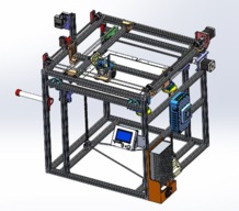
  1. Markal

    Markal New
    Builder

    Joined:
    May 5, 2018
    Messages:
    12
    Likes Received:
    1
    Hi Neil

    First off, Thanks for sharing your design. I was researching an Ultimaker type design when I came across yours. Your rigid XY design spoke to me the minute I saw it and I knew it had to be a good idea. That plus the larger print area.

    So, I have started to build Dash-X. I have chosen to go with 4 x 8mm Z axis screws rather than 3 x 10mm which just seems logical seeing how I have them in my parts bin already. I just need to modify the adjusting screw and the leadscrew brackets to take the smaller diameter. I think I saw you comment somewhere that you have also changed to 4.

    I have also chosen to try with 12v electrics and a 240v heated bed as I have a bucket full of Arduinos and Ramps boards and know my way round them pretty well now. All the fans etc I have are also 12v so I am sure it will not compromise your design by staying with what I know.

    This design of bed adjusting is hopefully easier to use than to fiddle with the tiny bed leveling screws on my other printers. Having got my first Delta printer with auto bed levelling, I am so looking forward to having that feature on this printer as well.

    Two questions if I may.

    Are you getting any sort of adjustment error with the Z adjusters or is the friction of the large wheels enough to keep everything in place? I can see that the potential for a combination of vibration and gravity trying to spoil things.

    What orientation are you printing the 'Pro-Duct'? I am battling with the support material blocking inside the duct and cannot clear it. Maybe it would work upside down perhaps?
     
    #61 Markal, Oct 6, 2020
    Last edited: Oct 6, 2020
  2. Neil Rosenberg

    Neil Rosenberg Journeyman
    Builder

    Joined:
    Dec 29, 2013
    Messages:
    180
    Likes Received:
    177
    I am replying via my cell phone, will do the best I can...

    I only use four z axis lead screws on VERY large machines, such as 24x24 inch. A 12x12 bed is better with three. Adjusting with four lead screws often results in distorting the bed. Remember, a plane is defined by three points.

    The z axis adjusting devices have a locking plate that provide friction, prevent unwanted turning. Please study the design.

    The duct is printed without internal supports (support from the bed only) to avoid the problem you mention. You need to study the part to make an informed decision about which orientation will print well, not have gaps, not have excessive support and have the grain in a direction to yield good working strength. Like many such parts, it will become obvious with careful observation.

    12v is fine, however the step motors will have less torque than at 24v.

    Hope this helps.
     
    #62 Neil Rosenberg, Oct 7, 2020
    Last edited: Jul 17, 2021
  3. Markal

    Markal New
    Builder

    Joined:
    May 5, 2018
    Messages:
    12
    Likes Received:
    1
    Thank you Neil. I will try it with 3 lead screws then.

    I tried printing the Pro-Duct upside down with support to bed only which looked like the most logical orientation for the angles, but still not getting a flow of air through one side. Will continue to experiment.

    I am aware and have printed the locking plates for the Z axis adjuster but did not pick up on the friction element. It definitely stops any sideways movement but did not seem to have much clamping action. Maybe I was just being too gentle or had not cleaned up the part sufficiently.
     
  4. Neil Rosenberg

    Neil Rosenberg Journeyman
    Builder

    Joined:
    Dec 29, 2013
    Messages:
    180
    Likes Received:
    177
    Hi again.

    As re the duct, the internal airways need to be clear of material for air to flow. Maybe make one, saw it in half to see what's going on.

    As re the locking plate, you may need to increase the amount of interference of the face plate on the wheel, so that tightening the mounting screws acts like an adjustable friction brake. That's the design intent anyway.

    Best
    Neil
     
  5. larosta

    larosta New
    Builder

    Joined:
    May 15, 2014
    Messages:
    10
    Likes Received:
    3
    Neil, nice systems oriented design. I am finishing up the brackets and hardware procurement. What length closed loop belt did you use for the z-axis drive and can you recommend a source for the belt?
     
  6. Neil Rosenberg

    Neil Rosenberg Journeyman
    Builder

    Joined:
    Dec 29, 2013
    Messages:
    180
    Likes Received:
    177
    Hi again. I buy most of my continuous belting from Stock Drive Products (shop.sdp-si.com)

    As measured by Solidworks, the "exact" belt length is 1187+/- mm. The nearest belts I could find on Stock Drive Products are A 6R51M590060 and A 6R51M605060 at 590 and 605 teeth respectively (2GT 2mm). These are 1180 and 1210 mm long respectively.

    Since the belt tensioning method allows for considerable variation in Z-Axis belt length, either should work fine.

    Regards
    Neil
     
    Markal likes this.
  7. Sascha Busse

    Builder

    Joined:
    Mar 23, 2021
    Messages:
    1
    Likes Received:
    0
    Hi Neil,

    I got in a little late, but am very excited and willing to build the Dash-X. Very nice that you posted the dimensions for the Z belt.
    What I am still missing are the dimensions of the closed belts for the X and Y axis. In Solid-Works project files I can't find any reference to the length. I have measured 1112,6mm. Is that correct?

    Edit: just realized that these belts aren't closed. *lol* So no problem here. Sorry for the elephant.

    Cheers
    Sascha
     
    #67 Sascha Busse, Mar 24, 2021
    Last edited: Mar 24, 2021
  8. Neil Rosenberg

    Neil Rosenberg Journeyman
    Builder

    Joined:
    Dec 29, 2013
    Messages:
    180
    Likes Received:
    177
    Hi Sascha, no problem, it's an easy mistake to make. Good luck with the build!
     
  9. tocguy

    tocguy New
    Builder

    Joined:
    Apr 4, 2021
    Messages:
    2
    Likes Received:
    0
    Hello Neil, this Dash-X design speaks to me as an engineer. From a mass-production perspective it may be viewed as "over designed" but as I'm sure you can attest, it's features are necessary to reliably produce the desired results. Looking forward to reading your book.
    Could you say a bit about the X, Y, and Z resolution and accuracy of this machine given the components employed? What changes have you considered in the years since it was conceived to improve upon its performance and/or address sub-optimal characteristics?

    I notice that the SketchUp collection does not contain a complete assembly. Where would I find a drawing of the complete Dash-X assembly?
     
    #69 tocguy, Apr 6, 2021
    Last edited: Apr 6, 2021
  10. Neil Rosenberg

    Neil Rosenberg Journeyman
    Builder

    Joined:
    Dec 29, 2013
    Messages:
    180
    Likes Received:
    177
    Hi there and thanks for the message.

    Dash-X represents one approach to improved rigidity and symmetry. It is however not the performance champ I had hoped for, particularly in speed. It's on the heavy side (kinematically), even with the Bowden extruder.

    I've been watching some of the amazing work being done now, such as the "Hevort" effort. Mindblowing really, and they're not alone. I think if I were to start up again I would look really closely at what they are doing. They're turning out good quality Benchies in about six minutes. Wow!

    As far as the cad models are concerned, I can send (post) other formats, which one would you like?

    Best
    Neil
     
    Mark Carew likes this.
  11. tocguy

    tocguy New
    Builder

    Joined:
    Apr 4, 2021
    Messages:
    2
    Likes Received:
    0
    Saw your FB post about HevoRT and was very impressed by what I've been reading/watching about it as well. It's good to see the craft advancing like that. An order of magnitude+ advancement in speed is no small increment.
     
  12. Steve the Kiwi

    Builder

    Joined:
    Apr 24, 2021
    Messages:
    4
    Likes Received:
    0
    Hi Neil,

    Great project! To date I have happily built the cube and have fitted corner gussets (on outside of cube) and this has stiffened up the build no end. I have parts on order too. I have not bothered with 3D printed bearing blocks etc that you put in the downloads but instead I have redesigned them so that I can and have made from 6061 aluminium on the CNC mill at work. When I am complete I will post those files up in step and iges so that they can be sucked down as required. I will also supply pdf files of the mechanical drawings. I feel this is only right considering the work you have put in! As for the leadscrews, I have seen differing reviews of the screws you have listed and I am down here in New Zealand can source diameter 8 x 8 lead very easily and think that these would also be suitable. Although gravity is on our side with this build, I am thinking also of anti-backlash nuts (not really needed) but would make it stand out more to visitors who view it.
    I am going make this a twin print head. There is the room to do so.
    This design is very suitable to going to 40mm square extrusion and a print size of 400mm even 500mm. I would look at transmission if going that big.
    I will post some images soon.
     
  13. Neil Rosenberg

    Neil Rosenberg Journeyman
    Builder

    Joined:
    Dec 29, 2013
    Messages:
    180
    Likes Received:
    177
    Hi Steve, I'm excited for you! There's nothing fundamentally wrong with using an 8x8 lead screw as long as you don't try to turn it too fast (whipping). I've seen postings on other forums where folks quantify the maximum length of lead screws for a given rotation speed.

    Yes, please do post your designs for the community at large. In fact, you may even want to create your own OpenBuilds build since you're advancing Dash in a number of respects.

    All good, thanks, and yes please do keep us all up-to-date on your progress. PICTURES!!!
     
  14. Markal

    Markal New
    Builder

    Joined:
    May 5, 2018
    Messages:
    12
    Likes Received:
    1
    Hi Neil

    Just a bit of feedback. The Mount for the BL Touch is not included in your files as an STL. I tried to convert it from the IGES but it was not all that successful. I got the basic shape to print, but the mounting holes did not convert. I had to drill them from the BL Touch in the end. I tried to import into Various programs to fix it but it would not tidy up nicely. The mount holes are visible in Cura but just do not print. It prints solid. Not sure if that is my ineptness in the conversion, or just the way IGES convert to STL's. Just mentioning that incase other builders also run into the same snag. no big deal. Tried to import it into TinkerCAD and MeshMixer but also did not import very well. Probably the conversion software settings I used I suppose.

    So, I have got the hardware for my Dash-X set up now, just starting the wiring using a Robin Nano V1.2 which I have available. I took your advice and picked up a 24v power supply. Was a nightmare sourcing carbon fiber rods with this pandemic messing up peoples stock availability. The project got side lined for a few months waiting for that. Managed to build a Workbee quickly in the mean time also using the Robin Nano so that will hopefully help with the learning curve of setting the Dash-x up.

    Looking forward to the first test print hopefully soon.
     
  15. kreeneytodd

    Builder

    Joined:
    Apr 7, 2020
    Messages:
    3
    Likes Received:
    0
    During my graduate degree I built and ran custom bioprinters. This is a fantastic design and would make one hell of a bioprinter. When I am through ill contact the old professor and see what he thinks about modifiying this build with our extrusion system. I'lm upgrading to a 32bit wireless board (so the printer can be sterilely operated while inside a biosafety cabinet) and adding dual extrusion. When im through ill upload the reprap configuration files for duet 2 and hotend assembly part files I design/modify. Ill upload some images later next week after my 30t 10mm bore pulleys arrive......Hardest hardware to come across those pullies.
     
  16. Neil Rosenberg

    Neil Rosenberg Journeyman
    Builder

    Joined:
    Dec 29, 2013
    Messages:
    180
    Likes Received:
    177
    Hi there. Sounds like you may have already solved the problem with the BLT mount. Sorry for the omission, I'm attaching it to this reply (too late I'm sure!). Best of luck with the build and do report as it goes. If I can help, you'll get a quicker reply if you email me directly: neil at vectorr dot com..
     

    Attached Files:

  17. Neil Rosenberg

    Neil Rosenberg Journeyman
    Builder

    Joined:
    Dec 29, 2013
    Messages:
    180
    Likes Received:
    177
    I agree, the cross-beam design is a good choice for a bio-printer. I'd be surprised if one wasn't already in development somewhere. Wishing you good luck with the build, and yes DO post your updates and improvements. Regards, Neil
     
  18. Markal

    Markal New
    Builder

    Joined:
    May 5, 2018
    Messages:
    12
    Likes Received:
    1
    Just an update to say thanks again for sharing your design and to let you know that I have the build working nicely. I have used 8mm screws for the Z axis but did have a few issues that a few pieces of paper sorted out with the screws not gripping, but thats my fault. I have also had issues with the magnetic build plate bubbling for some reason, again not a design fault, but most likely the quality of the Chinese component.

    I have it working with a touch screen Robin Nano and apart from fluffing the set up of the touch sensor (got all my X and Y settings mixed up so changing X settings was upsetting the Y calibration, rookie mistake.) I think it is a really successful build. Adapted power supply housing etc from Thingiverse to suit and now all self contained.

    I am inspired enough now to add dual hot end and extruder so I can print two colours. I have found a hot end that looks like it will be a direct fit. BIGTREETECH® 2 In 1 Out Hotend Extruder Dual Color 1.75MM 40W - 24V

    Once I have that working, I will post photos of my build.

    Thanks again.
     
    #78 Markal, Nov 7, 2021
    Last edited: Nov 15, 2021
  19. kreeneytodd

    Builder

    Joined:
    Apr 7, 2020
    Messages:
    3
    Likes Received:
    0
    Awesome! How do you plan on mounting the hot ends? I would like to try a few designs, I'm looking for the most versatile for all sorts of filaments. I would to have one dual extrusion assembly tailored specifically for one water soluble filament extrusion. My experience with those as supports has been a complete game changer but, they can be finicky and annoying to deal with.
     
  20. Markal

    Markal New
    Builder

    Joined:
    May 5, 2018
    Messages:
    12
    Likes Received:
    1
    That 2 In 1 Out Hot-end Extruder is a two in one out hot-end, sorry, my haste to post and misleading labelling on the website calling it an extruder.

    It is the only hot-end I could find that looked like it would be almost an exact match to the existing hot-end.

    It even comes with dual Bowden tubes so I have high hopes at a relatively simple modification.

    I have already mounted the second extruder and reel mount so as soon as it arrives, I can hopefully get the Robin Nano to cooperate and it will be working.

    This one will also mix colors so that could be interesting as well.

    The whole dual color operation looks like being a new challenging experience working out settings and designs in Cura. Looking forward to the challenge.

    Report back, the dual hotend ALMOST an exact fit. I have had to reprint the XY carriage with the mounting holes 2mm wider, so each hole moves out 1mm. Am printing it now, will hopefully get to fit it this week still.
     
    #80 Markal, Nov 8, 2021
    Last edited: Nov 15, 2021
  21. kreeneytodd

    Builder

    Joined:
    Apr 7, 2020
    Messages:
    3
    Likes Received:
    0
    Sorry for the late response, a few parts I ordered took a very long time to reach me but as of last week everything is in. I looked at those but haven't pulled the trigger on anything just yet. I have off of work so I plan on doing some serious damage to this machine. My build is coming along nicely now and if the z axis belt does not give me too much trouble tomorrow ill start the wiring nightmare and then onto configuring the duet 3. The first modification I plan on making is mounting 3 stepper motors atop the leadscrews. I want fully automatic bed leveling and if the printer allows it, it should offer us more z axis to print with. I plan on encasing this printer and replacing the abs components I currently have with higher temperature resistant filaments to print the more difficult polymers. This truthfully is a great design, the carbon fiber rods are such a great touch. fantastic torsional strength without the added vibration that comes with stainless steel rods. In my experience most of the flaws from cartesian style printers all stem from the kinematics and niels design really counters those issues.

    I hope this build gains popularity amongst the community, it would be nice to have multiple design modifications sourced similar to the voron community....and for half the price!
     
  22. Markal

    Markal New
    Builder

    Joined:
    May 5, 2018
    Messages:
    12
    Likes Received:
    1
    How Difficult is it to find 3mmx30mm hex head screws, that is all that is stopping me from mounting this dual extruder. All my suppliers seem to stop at 3x25mm. Now I have finished work and have some time to concentrate and get this finished, everyone is closed so will have to wait for new year.

    For any one wanting to try the dual hotend, that is all that is required, to move the one mounting hole out 2 mm and replace the 3x25mm screws with 3 x 30mm and of course fit a second extruder.
     
  23. Peter Van Der Walt

    Peter Van Der Walt OpenBuilds Team
    Staff Member Moderator Builder Resident Builder

    Joined:
    Mar 1, 2017
    Messages:
    14,001
    Likes Received:
    4,112
    Openbuildspartstore.com has, doesn't close down, and will be able to sort you out. See M3 Cap Head Screws
     
  24. Markal

    Markal New
    Builder

    Joined:
    May 5, 2018
    Messages:
    12
    Likes Received:
    1
    Hi Peter, Thanks, but I am in Cape Town, I think the R1,500 courier from the US is a bit excessive on a couple of screws :D.

    (Remember Me? I purchased your small orange 250mmx250mm CNC when you were still in Durban.)
     
    Peter Van Der Walt likes this.
  25. Peter Van Der Walt

    Peter Van Der Walt OpenBuilds Team
    Staff Member Moderator Builder Resident Builder

    Joined:
    Mar 1, 2017
    Messages:
    14,001
    Likes Received:
    4,112
    Sorry! I didn't check your location :)

    Oh wow, small world and great Reunion! I do recall you actually! Oh those were fun days!

    Sorry, I don't know CPT based suppliers that may still be open, Boltfast maybe?
     
  26. Steve the Kiwi

    Builder

    Joined:
    Apr 24, 2021
    Messages:
    4
    Likes Received:
    0
    Hi folks, I too am making good progress on this printer. I am going to create my own build page here. As can be seen, I have not 3D printed parts but have made them on a CNC mill from aluminium. I am making a few other changes by fitting a liquid cooled printhead and electrically I will have 24VDC busbars running through a Pi. As for the carbon rods. Wow! So nice. I have also spent some time making sure the X and Y axis movements are smooth and again once the two are linked, making sure that they still continue to be smooth.
     

    Attached Files:

  27. dprice

    dprice New
    Builder

    Joined:
    Oct 23, 2019
    Messages:
    22
    Likes Received:
    8
    Most parts ordered except for electronics and bed. Should be building in a week or so....most of the printed parts were done a year ago. The wife has recently started playing with the Ender 3 and wanted to try 2-color prints so that pushed me over the edge seeing that it appears to be a pretty simple mod.

    Happy holidays to all.
     
  28. dprice

    dprice New
    Builder

    Joined:
    Oct 23, 2019
    Messages:
    22
    Likes Received:
    8
    I'm finishing up the mechanical assembly and starting on the electronics. I went with the BTT Octopus V1.1 board...plenty of flexibility if I go with dual extruders and/or decide to use the spare outputs to rig up a testing/repair station for the growing collection of clogged Ender 3 hotends. This is my first attempt at a printer build (I was warned!). Does anyone have something of a cheat sheet for suggested settings for Marlin 2.0? I'm sure I'll be spending plenty of time in YTU to figure it out.
     
  29. Neil Rosenberg

    Neil Rosenberg Journeyman
    Builder

    Joined:
    Dec 29, 2013
    Messages:
    180
    Likes Received:
    177
    How exciting! Yes, Youtube is probably the best place to look for advice on Marlin settings. A quick search unearthed many good videos.
    Good luck!
     
  30. Neil Rosenberg

    Neil Rosenberg Journeyman
    Builder

    Joined:
    Dec 29, 2013
    Messages:
    180
    Likes Received:
    177
    I'm getting ready to post a major update to Dash-X, haven't decided whether to post it as a mod to this device, or copy it all with the changes to a new unit. I'll post here when it's ready.
     

Share This Page

  1. This site uses cookies to help personalise content, tailor your experience and to keep you logged in if you register.
    By continuing to use this site, you are consenting to our use of cookies.
    Dismiss Notice