Welcome to Our Community

Some features disabled for guests. Register Today.

C-Bot

Discussion in '3D printers' started by Carl Feniak, Sep 29, 2014.
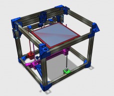
  1. Bravojul

    Bravojul New
    Builder

    Joined:
    Jul 7, 2016
    Messages:
    13
    Likes Received:
    8
    Thank you. I am afraid the heat could radiate under the bed and damage something on the bench or the electronic.
     
  2. Spiffcow

    Spiffcow Well-Known
    Builder

    Joined:
    Dec 27, 2015
    Messages:
    214
    Likes Received:
    92
    So.. Anyone got a Y bar mod for a cell phone holder so you can cheat at Pokemon Go? Kidding.. Well, half kidding.
     
    Carl Feniak likes this.
  3. Star Crator

    Builder

    Joined:
    Feb 28, 2015
    Messages:
    39
    Likes Received:
    10
    with a few zip-ties... and the direct-drive carriage, anything is possible!
     
    Spiffcow likes this.
  4. Austin Seagers

    Austin Seagers Well-Known
    Builder

    Joined:
    Oct 13, 2015
    Messages:
    88
    Likes Received:
    48
    Not that difficult if you have an extra bar of 1500mm extrusion, a spare stepper, belt, and pulley.

    Remember typical phone GPS accuracy is never better than +- 1m. Something about it being a risk to national security if civilians have access to greater accuracy GPS systems.
     
  5. DarkAlchemist

    DarkAlchemist Well-Known
    Builder

    Joined:
    Aug 2, 2014
    Messages:
    401
    Likes Received:
    22
    I had heard that was more like 10 meters or roughly 35 feet whereas the military has it less than 1 meter.
     
  6. DarkAlchemist

    DarkAlchemist Well-Known
    Builder

    Joined:
    Aug 2, 2014
    Messages:
    401
    Likes Received:
    22
    Apparently the Tevo Tarantula is a bad word on these forums since no one has replied to my thread in General but I was talking with someone and he brought up some valid points about these wheels Openbuilds is selling and repeatability at high speeds (100mm/s or more).

    "The problem with wheels system is the way it needs to be installed. Of course you can do with a hole cutting to mount it exactly without the eccentric nut. But ultimately, those nuts are ones that you need to constantly check to ensure they are tight fitting and there are no wearing on the wheels or the aluminium profile. "
     
  7. Austin Seagers

    Austin Seagers Well-Known
    Builder

    Joined:
    Oct 13, 2015
    Messages:
    88
    Likes Received:
    48
    This is the C-Bot build forum. No relation to the Tevo afaik?

    Carls models have a drafted fixing surface for the bolts that hold the wheels in place, meaning as you tighten the bolt, the hole centre of the wheel moves towards the rail. A non-issue in my book
     
  8. DarkAlchemist

    DarkAlchemist Well-Known
    Builder

    Joined:
    Aug 2, 2014
    Messages:
    401
    Likes Received:
    22
    Nope, no relation but has been brought up on this thread.

    So, how does his differ from the way Openbuilds shows it being done with the larger hole and the concentric nut? If actually better Mark Carew should know about this so he can implement it instead of the other flawed system.
     
  9. Austin Seagers

    Austin Seagers Well-Known
    Builder

    Joined:
    Oct 13, 2015
    Messages:
    88
    Likes Received:
    48
    Just wanted to re-visit the steel and fibre belt info me and @CapnBry were talking about a few pages back.

    My black fibre belts came in last night, with some 16T toothed and non-toothed idlers. I noticed that the new black belt was ever so slightly narrower than the steel belts. I didn't think to measure the difference, but will do if anyone is interested :/

    The reason i decided to swap the idlers, was because the two flanged bearings i was using were too close to one another, and the belt never really sat betwen the two flanges. This deformed the steel belt a bit, and gave me some weird patterns on exterior walls of prints. Also, getting idlers into the right place and getting an M3 bolt through them is so much easier than fiddling with 2x flanged bearings and a spacer to achieve the same result. 16T pulleys are very close OD to F623ZZ bearings so no re-printing of brackets etc.

    Quickly swapped everything around, and snapped a few pictures.

    Minimum bend radius is so much lower on these fibre belts, and they flex so much more, and don't hold their shape at all. The steel ones, could be bent to a tight radius, and when released, would have deformed slightly and tend to hold the bend you applied.

    Engagement with the 16T pulley on the XY steppers is now significantly better.

    The biggest improvement is resistance in XY moves. Previously, when the motors are un-powered, moving the XY carraiges felt like there was quite a lot of resistance. Not immovable, but significantly more than when the belts were not installed. Having changed to the fibre belts, this resistance is significantly reduced, and feels similar to the amount of resistance on previous printers I've had/used. My guess is this came from the belt being bent too abruptly around idlers.

    Here's a few pictures showing the changes. Excuse the mess. It's a WIP
    Imgur: The most awesome images on the Internet
    Imgur: The most awesome images on the Internet
    Imgur: The most awesome images on the Internet
    Imgur: The most awesome images on the Internet
     
    #2949 Austin Seagers, Jul 14, 2016
    Last edited: Jul 14, 2016
    CapnBry and Carl Feniak like this.
  10. DarkAlchemist

    DarkAlchemist Well-Known
    Builder

    Joined:
    Aug 2, 2014
    Messages:
    401
    Likes Received:
    22
  11. Austin Seagers

    Austin Seagers Well-Known
    Builder

    Joined:
    Oct 13, 2015
    Messages:
    88
    Likes Received:
    48
    It's in my post above. I don't use carls models directly, as i re-did them in solidworks, but used the same idea, whereby if a wheel is fixed by a bolt located with a pair of plates either side of the wheel, you can add the "eccentricity" on the faces of the plate that the bolt fastens to.

    Take a peek at the X carriage plate, and you'll see 2 (IIRC) tapered fixing surfaces around the M5 bolt holes, which ensure that as the bolt is tightened, the underside ofthe bolt head moves along the taper and thus, towards the rail, adding a pre-load on the wheel. Granted, the pre-load is added as a function of fixing tightness on the assembly of the carriage, but it costs nothing to do.

    I believe the M5 bolt holes also aren't circular, and are actually a slight 5mm diameter slot. Allowing the bolt to move towards the rail when tightened.

    Where anyone might need the spacers, is if you're not using carriages with a fixing plate either side of the wheel. As in the Z-carriage. But really, you can just print the second plate and buy a few longer M5 bolts, rather than have to buy expensive spacers.

    Yea, everything is printed in PETG. Can't beat it for strength
     
    #2951 Austin Seagers, Jul 14, 2016
    Last edited: Jul 14, 2016
  12. MaryD

    MaryD OpenBuilds Team

    Joined:
    Apr 13, 2016
    Messages:
    649
    Likes Received:
    639

    Tevo is is no way affiliated with OpenBuilds nor do they use OpenBuilds parts.
     
  13. Spiffcow

    Spiffcow Well-Known
    Builder

    Joined:
    Dec 27, 2015
    Messages:
    214
    Likes Received:
    92
    I didn't get the impression that talking about Tevo is a problem.. Just that it's in no way relevant to this board.
     
    AK Eric likes this.
  14. Spiffcow

    Spiffcow Well-Known
    Builder

    Joined:
    Dec 27, 2015
    Messages:
    214
    Likes Received:
    92
    I didn't realize that was the reasoning for that pattern on the adjustable side.. That's pretty cool.
     
  15. Star Crator

    Builder

    Joined:
    Feb 28, 2015
    Messages:
    39
    Likes Received:
    10
    Right, so, my aluminum plate came in, so did the countersink drill bit I ordered for it. However, my incompetence with a drill struck again! 3 of the holes are good enough to be usable, the last was either drilled to far out compared to the others, and caused major problems with my ability to level the bed, so I had to remove it, and now I have 3-point bed leveling, but the screws are in the corners, so I can get it close to perfect, but not quite there. The added weight (I think) of the aluminum plate compared to the glass bed I was using before also caused some problems with my Z-endstop screw, but I was able to fix that with a spare T-nut I had laying around.

    Other than the bed taking a long while to heat up to temperature, the PrintBite seems to work well, but i'll do a larger print on it tomorrow to see what happens.
     
  16. Chris Roadfeldt

    Chris Roadfeldt Journeyman
    Builder

    Joined:
    Dec 29, 2015
    Messages:
    182
    Likes Received:
    102
    You might have done this already. But can you flip the bed over and try the counter sink again?
     
    Star Crator likes this.
  17. Spiffcow

    Spiffcow Well-Known
    Builder

    Joined:
    Dec 27, 2015
    Messages:
    214
    Likes Received:
    92
    How sticky is the back? Like of you needed to could you take it off? I had a bad experience with BuildTak once that makes me wary to stick anything directly to the bed
     
  18. Star Crator

    Builder

    Joined:
    Feb 28, 2015
    Messages:
    39
    Likes Received:
    10
    I was going to, but one of the holes that messed up needed to be drilled outward more, but the new hole would have been close enough to the old one that it would have just shifted into it.

    With the three screws I can use, it doesn't seem like it will cause any wobble issues, the only direction the bed can mostly freely travel in is up and down, but it still takes some doing. If wobble is an issue and I need that other screw, I'll invest in a drill guide and try to re-do the holes, if that fails, I'll just saw the corners off and go back to using clips

    The adhesive is very sticky, if I peeled the PrintBite off the aluminum, I'd probably need to get another adhesive sheet
     
  19. Star Crator

    Builder

    Joined:
    Feb 28, 2015
    Messages:
    39
    Likes Received:
    10
    I may have thought up a solution to my problem... I was thinking I could use a routing bit (on say a dremel) with a 45deg bevel on it, and another that is ~3mm diameter and just rout out the corners into a slot, if I line them up correctly, they should be able to hold the bed well, and auto-correct some slight alignment issues with the hole placement, or at the very least, I could just rout out the bad holes in the direction that would best correct the alignment problem.
     
  20. sLpFhaWK

    sLpFhaWK New
    Builder

    Joined:
    Feb 16, 2016
    Messages:
    18
    Likes Received:
    3
    Just installed the roll feeder mount system. Pretty awesome I wish I did it sooner.

    Next project to tackle is some sort of Go Pro mount system for my Xiaomi action camera. Have any of you guys/gals found one that works? I have scrapped some random parts together from thingiverse and it works but I don't care for it.. Please let me know. Thanks!
     
  21. markdoll01

    Builder

    Joined:
    Jul 16, 2016
    Messages:
    21
    Likes Received:
    29
    Hi All,

    I just want to say thank you for this amazing design. I went and build the D-Bot design and am super happy with it. A week ago I went and changed the original D-Bot bowden to direct drive and I am getting now these ripples which I just can't get away. I tried the following:
    1) Super tightened my belts
    2) Tried smaller stepper motor - still quite heavy going at about 240 grams
    3) Swapping stepper drivers (using the DRV8825 set at 1/32)
    4) Changed stepper current
    5) Changed Jerk and Acceleration from high to low - no difference
    6) Tried printing fast and slow
    None of these made a big difference - only the tightening of the belts made a small difference. I then did a quick and dirty move back to bowden and the ripples were gone. Is anybody else having this, I really want to move over to direct drive. Is the only answer a pancake stepper or did somebody get success with a standard nema 17 stepper?
    IMG_1700.JPG
     
  22. Spiffcow

    Spiffcow Well-Known
    Builder

    Joined:
    Dec 27, 2015
    Messages:
    214
    Likes Received:
    92
    I always used direct drive so I just assumed this was normal.. I believe I saw an improvement in these during my experiments with a wheel-less carriage, but I need to do more before I can confirm that
     
  23. markdoll01

    Builder

    Joined:
    Jul 16, 2016
    Messages:
    21
    Likes Received:
    29
    Just for comparison, here is a pic of the same part (at bout 80% through when I canceled it) after I did the quick dirty swap back to bowden. The temperature was not right so that is why the part is shiny at the bottom and mat black further up - but the line as nice and smooth. I got some amazing prints with the bowden but I do not like the oozing/blobbing etc. I have the bowden tuned nicely but depending on what parts I print I sometimes need to change the retraction etc. . With the direct drive it is much nicer as for one setting for all and I want to start printing flexible filament .

    IMG_1701.JPG
     
  24. Star Crator

    Builder

    Joined:
    Feb 28, 2015
    Messages:
    39
    Likes Received:
    10
    I'm running an E3D titan with a pancake stepper, and I don't see a pattern like that one mine, but any pattern is kind of hard to see on my prints besides slight ghosting, but the PLA I'm using isn't shiny at all at the speeds/temp I print at. My stepper + extruder + front carriage plate weigh a little less than a 42mm nema17 motor.

    I'm running an Azteeg x5 v1.1, it has DRV2285 drivers, at 24V.

    Something you may want to try, if you can, is to attach weight to the carriage, so it would be close to when you run direct drive, and print with the bowden to see if the pattern is apparent, if it is, then it's probably a weight thing.
     
    Muh_3d likes this.
  25. markdoll01

    Builder

    Joined:
    Jul 16, 2016
    Messages:
    21
    Likes Received:
    29
    Thanks, that is a great idea. I will revert back fully to the original bowden setup tomorrow and then do tests with adding weights.
     
    Spiffcow and Muh_3d like this.
  26. Spiffcow

    Spiffcow Well-Known
    Builder

    Joined:
    Dec 27, 2015
    Messages:
    214
    Likes Received:
    92
    Please let us know how it goes.

    Also, looking at both pics, it appears to me that the ripples exist in both, but are much more pronounced in the direct drive pic than in the bowden one. Is this accurate? Or am I looking at the wrong thing?
     
  27. markdoll01

    Builder

    Joined:
    Jul 16, 2016
    Messages:
    21
    Likes Received:
    29
    I will definitively let know what the outcome is - hopefully in the next two days. The second picture is not a very good one - in the centre there is a shallow portion that needs to be like that and it is not "ripples" . In real life there is a huge difference between the bowden and direct dive and the ripples that I am getting.
     
  28. markdoll01

    Builder

    Joined:
    Jul 16, 2016
    Messages:
    21
    Likes Received:
    29
    Ok, I am back on bowden but kept the gantry the same - just moved the motor back to the side and fitted a new bowden for full length. I will start adding weights tomorrow - waiting for a friend to lend me a scale.

    Here is a photo of the same part with the direct drive print on the left and bowden on the right.

    IMG_1707.JPG
     
    Carl Feniak, Muh_3d and Spiffcow like this.
  29. Spiffcow

    Spiffcow Well-Known
    Builder

    Joined:
    Dec 27, 2015
    Messages:
    214
    Likes Received:
    92
    What's really weird about those ripples is they appear to be diagonal.. The ripples I get with my direct drive are less pronounced, but vertical..

    It's hard to tell from the photo, are the ripples raised enough that the surface is bumpy?

    Also, do they appear along the X axis, Y axis, or both?
     
  30. markdoll01

    Builder

    Joined:
    Jul 16, 2016
    Messages:
    21
    Likes Received:
    29
    Yes they are. One can feel them where as the other print feels quite smooth. Very strange pattern . Could the heated bed springs have something to do with it - not strong enough ? Just guessing here. Will see tomorrow what the adding wight does and from where it starts.

    And yes, they are the same on X and Y .
     
    #2970 markdoll01, Jul 18, 2016
    Last edited: Jul 18, 2016

Share This Page

  1. This site uses cookies to help personalise content, tailor your experience and to keep you logged in if you register.
    By continuing to use this site, you are consenting to our use of cookies.
    Dismiss Notice