Welcome to Our Community

Some features disabled for guests. Register Today.

BAFP 3D Printer

Discussion in '3D printers' started by Steven Bloom, Nov 24, 2015.
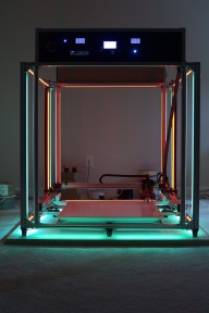
  1. Steven Bloom

    Steven Bloom Journeyman
    Builder

    Joined:
    Dec 18, 2014
    Messages:
    194
    Likes Received:
    104
    Some. So we are waiting on a few things. We had to get rid of the stock pullies and go for ones that were 6.5mm wide. This way a 6mm belt would not move around so much. We ordered a few 1524mm endless belts for the z axis. We just ordered the proximity sensor for the z axis. Once the new pulleys and belts come in we will wire the motors and download the firmware. Aftwe that we just need to mount the the hot ends and heatbed
     
  2. Val Cocora

    Val Cocora Well-Known
    Builder

    Joined:
    May 19, 2014
    Messages:
    172
    Likes Received:
    28
    as for myself, just returned this evening to canada.
    tomorrow is business as usual.
     
  3. jezter6

    jezter6 New
    Builder

    Joined:
    Jan 31, 2016
    Messages:
    23
    Likes Received:
    3
    Great build! This one looks to be much more my speed, particularly the use of off the shelf parts instead of a crapton of printed parts.

    A few questions, hopefully you guys wouldn't mind helping out with.

    1) Regarding weight - for those of us who are going to use not only slightly smaller dimensions, and a single E3D v6 hotend, is the 2040 rail for X and Y truly necessary to hold without bowing? I read above where you guys were lifting like 13 pounds, and I wonder how much of that could be reduced by dropping some rail weight?

    2) Same question with the Z guides. Considering the lead screws are carrying the overall brunt of the weight, it seems like those rails are really to keep the ends of 1 axis from twisting and just rolling nicely up a guided rail. Since those pieces aren't structural, is there a need for 2040 rail in that particular instance?

    3) What are your thoughts on moving the Z motors and belts to the top of frame? Having pulleys above the frame above the top bearings allow one to easily replace a closed loop belt without having to take the lead screws off. Also, considering reduction in the gantry weight with #1, it seems like a single motor driving larger lead screw pulleys on a single loop would be preferable from a keeping motors synced standpoint.

    4) What about converting to a corexy style system? Seems like reducing the motor count by 1 would help with both reduced Z lifting weight and (from what I understand) increased speeds?

    5) Will you be posting an updated BOM list?
     
  4. maleuffy

    maleuffy New
    Builder

    Joined:
    Jan 16, 2016
    Messages:
    8
    Likes Received:
    2
    Question: How much does the frame wobble? Look like a big frame and from what I know aluminium isn't the sturdiest material out there...
     
    #64 maleuffy, Feb 11, 2016
    Last edited: Feb 13, 2016
  5. Steven Bloom

    Steven Bloom Journeyman
    Builder

    Joined:
    Dec 18, 2014
    Messages:
    194
    Likes Received:
    104
    Well we have some new pics to post. The BAFP 3D printer is now able to move via motors thru the control panel. Next step is the limit switches and the extruders and hot ends.

    _DSC1999.jpg

    _DSC2000.jpg

    _DSC1997.jpg

    _DSC1998.jpg

    _DSC1995.jpg

    _DSC1996.jpg

    _DSC2001.jpg
     
    Mark Carew and Val Cocora like this.
  6. Steven Bloom

    Steven Bloom Journeyman
    Builder

    Joined:
    Dec 18, 2014
    Messages:
    194
    Likes Received:
    104
    1) it might be able to be reduced but we don't want bowing. Its around 13 lbs on the Y's becase of 3 motors for the x and y's as well as two motors for the extruders plus the extruders are aluminum.

    2) we could have went with 2020 for the z holders but went with 2040 so we could insert some nice acrylic inside the unused channels.

    3) We like the motors un the bottom where they are under and out of the way. Its easy enough to put a belt on and I personally have not had one break in 2 years

    4) Maybe it would but its working, why bother.

    5) Yes, we will post everything once we are complete. Still ironing some things out.

    Thanks Steven
     
  7. Val Cocora

    Val Cocora Well-Known
    Builder

    Joined:
    May 19, 2014
    Messages:
    172
    Likes Received:
    28
    uh, steven, second picture from the bottom...is that the panic button from an iphone?
     
  8. Steven Bloom

    Steven Bloom Journeyman
    Builder

    Joined:
    Dec 18, 2014
    Messages:
    194
    Likes Received:
    104
    We will have a video soon. I have not seen too much wobble yet and we are moving at a constant 100mm per sec. That seems fast enough for now. Once we have it printing we will see if we can turn it up.

    Thanks Steven
     
  9. Steven Bloom

    Steven Bloom Journeyman
    Builder

    Joined:
    Dec 18, 2014
    Messages:
    194
    Likes Received:
    104
    I am not sure on that. Tim got a nice lighted switch. He plans on putting in a bunch of LED's. Its going to look very cool.
     
  10. Val Cocora

    Val Cocora Well-Known
    Builder

    Joined:
    May 19, 2014
    Messages:
    172
    Likes Received:
    28
    teasing aside, i love your work, guys.
    looking forward to see a video of it in action.
     
  11. Steven Bloom

    Steven Bloom Journeyman
    Builder

    Joined:
    Dec 18, 2014
    Messages:
    194
    Likes Received:
    104
    Here are two videos


    Mark Carew and Val Cocora like this.
  12. maleuffy

    maleuffy New
    Builder

    Joined:
    Jan 16, 2016
    Messages:
    8
    Likes Received:
    2
    can it move in Z? have you got a video of that! Pretty cool!
     
  13. Tim N

    Tim N New
    Builder

    Joined:
    Nov 17, 2015
    Messages:
    17
    Likes Received:
    16
    Here is a new vid testing homing X/Y and Z movement...

     
    Val Cocora and Steven Bloom like this.
  14. Mark Carew

    Mark Carew OpenBuilds Team
    Staff Member Moderator Builder Resident Builder

    Joined:
    Jun 28, 2013
    Messages:
    2,745
    Likes Received:
    2,410
    Looks like its working really well @Tim N your almost there! Throw a hot end on this bad boy and lets see some HUGE prints!!! :thumbsup:
     
  15. Tim N

    Tim N New
    Builder

    Joined:
    Nov 17, 2015
    Messages:
    17
    Likes Received:
    16
    Thanks, Mark.

    Installed the 26" boro glass, heat pad and 1 hot end...

    [​IMG]
     
  16. Steven Bloom

    Steven Bloom Journeyman
    Builder

    Joined:
    Dec 18, 2014
    Messages:
    194
    Likes Received:
    104
    Wow, the glass with the heatbed look great !!!! Love how it fits on those aluminum. How are the glass hold downs doing ????
     
  17. Val Cocora

    Val Cocora Well-Known
    Builder

    Joined:
    May 19, 2014
    Messages:
    172
    Likes Received:
    28
    can't wait for my chunk of glass to show up this week.
    until then, dry tests..


    Steven Bloom likes this.
  18. Tim N

    Tim N New
    Builder

    Joined:
    Nov 17, 2015
    Messages:
    17
    Likes Received:
    16
    Here is a video of the printer homing X/Y/Z and auto bed leveling...we are really almost there...


    Val Cocora and Steven Bloom like this.
  19. Val Cocora

    Val Cocora Well-Known
    Builder

    Joined:
    May 19, 2014
    Messages:
    172
    Likes Received:
    28
    that glass looks so good on the bafp it makes me drool..
    my glass is coming today, brought by a buddy of mine.
    beer is already cold, can't wait to finally see how the glass sits on the bed, after 2 years of work.
    will post pictures soon, hopefully tonight if sober.
     
  20. Val Cocora

    Val Cocora Well-Known
    Builder

    Joined:
    May 19, 2014
    Messages:
    172
    Likes Received:
    28
    well, glass came as promised, better post some pics before that beer bottle becomes a 12 pack.
    ***, after a hard day of work...
    picture351.jpg

    picture353.jpg


    picture352.jpg
     
    Steven Bloom likes this.
  21. Steven Bloom

    Steven Bloom Journeyman
    Builder

    Joined:
    Dec 18, 2014
    Messages:
    194
    Likes Received:
    104
     
  22. Steven Bloom

    Steven Bloom Journeyman
    Builder

    Joined:
    Dec 18, 2014
    Messages:
    194
    Likes Received:
    104
     
  23. Val Cocora

    Val Cocora Well-Known
    Builder

    Joined:
    May 19, 2014
    Messages:
    172
    Likes Received:
    28
    glass weighs around 90 lbs.
    platform is calculated for about 550 pounds, and each lead screw is good for about 250 lbs.
    it runs great, the frame is reinforced by design, plus an extra two top rails (black) so there's no shaking while running.

    will post more vids soon.
     
    #83 Val Cocora, Mar 19, 2016
    Last edited: Mar 19, 2016
  24. Val Cocora

    Val Cocora Well-Known
    Builder

    Joined:
    May 19, 2014
    Messages:
    172
    Likes Received:
    28
    well, if my math is any good, glass density is 2500 kg/m^3
    my glass is 1332x1170 mm, 12 mm thick, which means a volume of 0.0187 m^3.
    multiplying that with density we get approx. 46.7 kg, or 102 lbs.
    i was worried the glass will have an inherent bow from tempering, but the glass guys did a really good job at keeping it straight.
    special order, only 250 canadian bucks plus a six pack for shipping.
     
  25. Val Cocora

    Val Cocora Well-Known
    Builder

    Joined:
    May 19, 2014
    Messages:
    172
    Likes Received:
    28
    speaking of glass, does anybody know where i could find some flat and round thermistors? the diameter would have to be around 5 mm max, to fit the 10 mm pass holes i allowed in the silicone pad especially for this purpose.
    the thermistors i have look more roundish and i am concerned about the contact patch with the glass. i'm hoping flat thermistors (thin film, maybe) will do a better job. thanks.
     
    #85 Val Cocora, Mar 20, 2016
    Last edited: Mar 20, 2016
  26. Val Cocora

    Val Cocora Well-Known
    Builder

    Joined:
    May 19, 2014
    Messages:
    172
    Likes Received:
    28
    hi justin, i'm hoping to find some small coin shaped thermistors, i have 8 pass holes, 10 mm diameter each, cut into the silicone pad especially for that.
    the coin, or disc, shaped thermistors, ensures a better contact patch with the underside of the glass.
    not so sure cylinder shaped thermistors would be that good at it.

    https://vikiwat.com/userfiles/productimages/1169/product_large_35992.jpg
     
  27. Val Cocora

    Val Cocora Well-Known
    Builder

    Joined:
    May 19, 2014
    Messages:
    172
    Likes Received:
    28
    i think i will enclose the thermistors i have in a little plastic tube, and run the lead wires down thru one inch of the cork insulation supporting the pad. the top of the thermistor will be flush with the top of the enclosing tube, and in contact with the under side of the glass. the silicone pad has eight 10 mm (3/8") diameter pass holes for an equal amount of thermistors, four in the corners and four around the center.
    in retrospect, i could have designed those holes somewhat larger, but i didn't want to bite too much into the heating area surrounding them.
    next heated pad will have a better design.
     
  28. Val Cocora

    Val Cocora Well-Known
    Builder

    Joined:
    May 19, 2014
    Messages:
    172
    Likes Received:
    28
    uh, just enclosed the thermistors in 3/16 shrink wrap. and since the lead wires are about 1 3/4" long and the cork it's going to go into is only 1 inch deep, it all works like a charm. the rest is just laying wires.
    couple of pictures attached, before and after.
    picture360.jpg

    picture363.jpg
     
    #88 Val Cocora, Mar 27, 2016
    Last edited: Mar 27, 2016
  29. Val Cocora

    Val Cocora Well-Known
    Builder

    Joined:
    May 19, 2014
    Messages:
    172
    Likes Received:
    28
    indeed, i used the shrink as a sleeve, and pulled it over both legs from the open end, then onto the thermistor itself, so both legs, or lead wires, are inside the shrink wrap.
    these lead wires come out of the thermistor at a divergent angle and the metal in them is quite steely, so they preserve a natural rigidity inside the shrink wrap. also, there is a space of about 3 mm (1/8") between them, but i've been thinking to insulate the lead wires separately prior to covering them, to prevent them from touching each other accidentally.
    the initial idea was to use some plastic tubes, 4 mm (5/32") inside diameter and 1 inch long, but then my sights literally fell on the shrink wrap tube laying around, and i said 'why not'.
     
  30. Tim N

    Tim N New
    Builder

    Joined:
    Nov 17, 2015
    Messages:
    17
    Likes Received:
    16
    Recent progress...

    [​IMG]

    [​IMG]

    [​IMG]

    [​IMG]
     
    Giarc, AK Eric, silopolis and 2 others like this.

Share This Page

  1. This site uses cookies to help personalise content, tailor your experience and to keep you logged in if you register.
    By continuing to use this site, you are consenting to our use of cookies.
    Dismiss Notice