Welcome to Our Community

Some features disabled for guests. Register Today.

C-Beam cnc

Discussion in 'CNC Mills/Routers' started by Kyo, Jun 24, 2016.
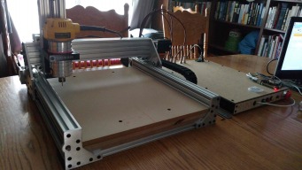
  1. EvanBruner

    EvanBruner Well-Known
    Builder

    Joined:
    Mar 26, 2016
    Messages:
    68
    Likes Received:
    66
    Kinda looks like paracord. You can take out the core and use it for sleeving.

    Check out mainframe customs or MDPC-x for some really high quality sleeving. The PC modding communities use those a lot, it's good stuff.
     
    #91 EvanBruner, Aug 10, 2016
    Last edited: Aug 11, 2016
  2. Kyo

    Kyo Veteran
    Staff Member Builder Resident Builder

    Joined:
    Feb 27, 2014
    Messages:
    673
    Likes Received:
    699
    James -- Sure which z-axis plates did you need?

    @Metalguru I don't really recall, I use to do custom wiring harness for restomods and engine swaps. This stuff was just left over. EvanBruner -- Yeah I have worked with paracord as well stuff is sweet to work with so many uses. :thumbsup:
     
  3. Kyo

    Kyo Veteran
    Staff Member Builder Resident Builder

    Joined:
    Feb 27, 2014
    Messages:
    673
    Likes Received:
    699
    It is alive! grbl is running smoothly. Only thing left to wire up are my aviation motor connectors and the start, hold, reset buttons. My bec is doa so I can not use the internal pi 3 as planned in tell I come up with another way to power it. I should have tested it when it arrived. Also the green led on two of my drivers are very dim in comparison to the other two drivers they all seem to work just fine, and they each have their own power connection so I am not sure what to make of that.

    Spoiler board is mounted and in place two M5x40mm bolts in the front and two more in the rear go right through both .5" mdf spoiler boards through the 1/2" tooling plate and bolt directly to the cnc frame tying it all together. If I was to do this again. I would skip the t-nuts here and simply tap the tooling plate with threads. Getting the t-nuts lined up was a pain.


    Attached Files:

    • 1.jpg
      1.jpg
      File size:
      105.2 KB
      Views:
      223
    • 2.jpg
      2.jpg
      File size:
      70.1 KB
      Views:
      212
    • 3.jpg
      3.jpg
      File size:
      173.1 KB
      Views:
      222
    • 4.jpg
      4.jpg
      File size:
      137.6 KB
      Views:
      216
    • 5.jpg
      5.jpg
      File size:
      112 KB
      Views:
      211
  4. Joe Santarsiero

    Joe Santarsiero OB addict
    Staff Member Moderator Builder

    Joined:
    Oct 30, 2014
    Messages:
    902
    Likes Received:
    196
    Great build. I used a similar mechanical layout. Proves to be very ridged.
    Those aviation plugs were a pita for me. I used 18ga which was most of the problem. I had to file down the openings on the jacket and take down the clamp tooth. Wetting the sockets and wire ends first definitely helped. A third hand helps too.
     
  5. Kyo

    Kyo Veteran
    Staff Member Builder Resident Builder

    Joined:
    Feb 27, 2014
    Messages:
    673
    Likes Received:
    699
    Yeah those aviation connectors can be a pain. While I don't have a vise or third hand to help hold them, I did find mounting them to the panel as a means to hold them in place helped a lot. As did your tip on tinning the pins and wire in advance. :thumbsup:


    And she is complete! Time to put her to work making parts for my next build :D I look forward to seeing everyone's build. It sounds like a few have already started. Don't forget to come back and post up !

    6.jpg

    Here is a quick look at the inside of my electronics box. Wiring was straight forward a bit unorganized as far as wire routing goes but I was limited by space. I wired the drivers up as was discussed in my prior post and videos. Here is another short video going over my components and settings ( drivers / grbl / ect ) If I left anything out you need me to cover just let me know. I downloaded the data sheet for each component and followed the directions nothing to complex with this controller ( phoenix cnc ).

    5.jpg


    In the end I can not recommend the bec I used ( doa, I suspect not up to the task for 24v ) nor can I recommend the power input plug I chose; very lose pins and overall poor quality. Those will be the first to be replaced.

    The Dewalt 611 has proven itself up to the task on my plate maker so I chose to run a dewalt on the Sphinx as well. I have thrown wood , mdf, acrylic, aluminium , ect at it with no problems. A excellent budget choice for a spindle.


    I can not wait to get started on my next build, I have already started the design phase. :D
     

    Attached Files:

    • 1.jpg
      1.jpg
      File size:
      112.9 KB
      Views:
      164
    • 2.jpg
      2.jpg
      File size:
      71.4 KB
      Views:
      157
    • 3.jpg
      3.jpg
      File size:
      186.6 KB
      Views:
      162
    • 4.jpg
      4.jpg
      File size:
      173.6 KB
      Views:
      158
    • 7.jpg
      7.jpg
      File size:
      114.8 KB
      Views:
      159
    MaryD, Mike Piechowski, Moag and 2 others like this.
  6. GrayUK

    GrayUK Openbuilds Team Elder
    Staff Member Moderator Builder

    Joined:
    May 5, 2014
    Messages:
    1,668
    Likes Received:
    627
    I can not see, but have you got any form of cooling in that control box? :rolleyes:
    If not, I think you should consider giving it at least one computer fan to eject/extract the heat that is going to build up in there. Plus, being of low height, it won't take long for those drivers to be stewing in their own heat. :(
    Gray
     
  7. Kyo

    Kyo Veteran
    Staff Member Builder Resident Builder

    Joined:
    Feb 27, 2014
    Messages:
    673
    Likes Received:
    699
    It should be getting some, but you are correct they are not shown in those photos. I need to take some updated photos. On the rear panel I am hoping to house a couple fans functioning as exhaust fans that will always be on when the controller is on.. Do you think I should add a intake fan on top as well?
     
    #97 Kyo, Aug 14, 2016
    Last edited: Sep 11, 2016
  8. GrayUK

    GrayUK Openbuilds Team Elder
    Staff Member Moderator Builder

    Joined:
    May 5, 2014
    Messages:
    1,668
    Likes Received:
    627
    For the sake of dust and debris, I'd avoid any holes in the top, unless you have a good filter for it.
    An intake fan in the side/front area would generate a cooling wave across all the components.
    Even just some holes near the front, preferably underneath, if it sits on feet. Maybe a better idea? Sucking cool air in again. :thumbsup:
    Gray
     
  9. Metalguru

    Metalguru Veteran
    Builder

    Joined:
    Dec 29, 2015
    Messages:
    752
    Likes Received:
    547
  10. Mark Carew

    Mark Carew OpenBuilds Team
    Staff Member Moderator Builder Resident Builder

    Joined:
    Jun 28, 2013
    Messages:
    2,744
    Likes Received:
    2,409
    @Kyo Love following along with the progress you've made here. The Sphinx build & build manual looks amazing my friend! :thumbsup:
     
  11. Kyo

    Kyo Veteran
    Staff Member Builder Resident Builder

    Joined:
    Feb 27, 2014
    Messages:
    673
    Likes Received:
    699
    Rummaging in my fan bin, I think I found just the right fan to pull fresh air in from the underside. I will see about getting it installed when I put in the new pi 3 power supply.

    Nice find, I have used hardblok in the past never would have thought to use in this way.. Now that I think about it I never have used it as intended. hahaha ( works great for plugging un needed ports on cast iron manifolds. )


    Thank you :D I have had a lot of fun building and documenting everything. I always enjoy taking something from a quick sketch to cad to final product. I am starting to think I enjoy the designing / building more so then even using the end project haha. Can not wait to get started on the next build. :thumbsup:
     
    #101 Kyo, Aug 16, 2016
    Last edited: Sep 11, 2016
  12. Mike Piechowski

    Builder

    Joined:
    Jun 11, 2016
    Messages:
    33
    Likes Received:
    22
    Too bad about the BEC not working, it is an elegant solution that requires no soldering or adjusting. As I mentioned earlier, I am using a BEC that has both a 5V and 12V output, and I have it plugged into my 24V supply.

    So far, no smoke. I haven't powered the Pi3 with it in a "production" mode yet, I'm just using it to provide 12V for the fan. I need to solder a JST-style power lead onto the Pi3 to hook it up, but I have been too busy cutting parts with the C-Beam to take it apart.

    Love that desktop background.
     
  13. Kyo

    Kyo Veteran
    Staff Member Builder Resident Builder

    Joined:
    Feb 27, 2014
    Messages:
    673
    Likes Received:
    699
    Yeah I was looking forward to using the bec I think I just got a bad one. I would not rule out trying another one.

    New step down converter came in the post today. Works excellently. No adjustments or soldering required with this unit either. Solid screw terminals and clear labeling. 12/24V input and 5V 10A output.
    I also got around to installing my panel mount dual usb ( keyboard and mouse ) and hdmi inputs. Cables turned out to be about a 20mm shy of reaching the rear panel so I had to do a little butchering of the front. If I measured my cables before hand, I could have included cut outs in the laser cutting of the front panel.

    With the pi3 installed internally and having built in wifi and Bluetooth I am able to send my gcode files over to the machine on my local network without having to transfer via usb or sd. I can get use to this :D
     

    Attached Files:

    • 1.jpg
      1.jpg
      File size:
      101.9 KB
      Views:
      163
    • 2.jpg
      2.jpg
      File size:
      106.7 KB
      Views:
      163
    • 3.jpg
      3.jpg
      File size:
      106.7 KB
      Views:
      160
    • 4.jpg
      4.jpg
      File size:
      98.1 KB
      Views:
      161
    Mike Piechowski, rozitt and GrayUK like this.
  14. Kyo

    Kyo Veteran
    Staff Member Builder Resident Builder

    Joined:
    Feb 27, 2014
    Messages:
    673
    Likes Received:
    699
    :thumbsup:
     

    Attached Files:

    Mike Piechowski likes this.
  15. Mike Piechowski

    Builder

    Joined:
    Jun 11, 2016
    Messages:
    33
    Likes Received:
    22
    Thanks for sharing the desktop pic!

    The Pi3 is a nice piece of gear. I haven't messed with the Bluetooth yet, but the WiFi sure makes it easy to get the gcode on the machine. While I typically run things with a local console, I've also run things via a remote desktop session, which is pretty cool.

    That is a MASSIVE DC/DC converter. Where did you find that one? I found a few smaller ones (5V 3A) on Amazon, I use them to power USB charging ports in the car. They'd probably run a Pi without any drama, but I haven't tried yet.
     
  16. Kyo

    Kyo Veteran
    Staff Member Builder Resident Builder

    Joined:
    Feb 27, 2014
    Messages:
    673
    Likes Received:
    699
    I picked it up on amazon for a few bucks. It has been up and running for a few days now. Excellent choice for powering a pi from either 12v or 24v power source like the OB 24v power supply I am running. It is not very large either; smaller then the pi itself. I ordered a second for the in car pi computer I am planning. :thumbsup:

    This is a direct link "Here" to the one I bought if you wanted to pick one up.
     
    #106 Kyo, Aug 18, 2016
    Last edited: Aug 18, 2016
    eddiejr likes this.
  17. Mike Piechowski

    Builder

    Joined:
    Jun 11, 2016
    Messages:
    33
    Likes Received:
    22
    Thanks for the link. I didn't see that version last time I was shopping for them, so I wound up with some smaller ones.
     
  18. C-Line

    C-Line New
    Builder

    Joined:
    Feb 3, 2014
    Messages:
    9
    Likes Received:
    0
    Hey Kyo, congrats on your great design and completed build!
    I'm planning a special purpose machine based on your design but with much longer Y-axes, and I'm trying to figure out where to store it in my shop. I won't need it very often and was thinking about hanging it on a wall when not in use. Do you see any reason why that would be a problem? Any changes/alterations I should consider? Do you know the total weight of your machine, excluding controls/electronics?
     
  19. Kyo

    Kyo Veteran
    Staff Member Builder Resident Builder

    Joined:
    Feb 27, 2014
    Messages:
    673
    Likes Received:
    699
    Thank you! I look forward to seeing your build ! The machine is definitely strong enough to be stored like that. I have seen some of the guys who received a shapeoko on youtube store their machine in the same way. It would have to be a strong hanging system! My small desktop machine weights in at 32 kilograms according to the scale (70lbs). Making the machine larger will add to that weight. I think some form of lifting table might be a better option over hanging on a wall. Or you could place it on a torsion box and use a chain hoist to lift it straight up suspended from the ceiling.
     
    #109 Kyo, Aug 18, 2016
    Last edited: Aug 19, 2016
  20. James_Hopkins

    Builder

    Joined:
    Jul 16, 2015
    Messages:
    28
    Likes Received:
    6
  21. Kyo

    Kyo Veteran
    Staff Member Builder Resident Builder

    Joined:
    Feb 27, 2014
    Messages:
    673
    Likes Received:
    699
    He makes a nice product and his stepper driver board is pretty sweet. I have thought about picking one up to run some nema 17 motors.

    But in all honesty if you wanted to run pololu style drivers instead of dedicated external drivers. I would pick up the Protoneer raspberry pi hat. It takes what would be 3 separate boards and a bunch of cabling and provides you with a nice compact package.
     
    Paul Stoller likes this.
  22. C-Line

    C-Line New
    Builder

    Joined:
    Feb 3, 2014
    Messages:
    9
    Likes Received:
    0
    Thanks for the info. What I may do is mount one end to the wall with hinges so that I can just fold it down when not in use. I'll try to post some pics when it's done (though it may be a while!)
     
  23. James_Hopkins

    Builder

    Joined:
    Jul 16, 2015
    Messages:
    28
    Likes Received:
    6
    Kyo, What size belt should i use if i make your z-axis belt reduction mount?
    And i should use a 20T on the motor and a 40T on the other end? GT3?
     
  24. Kyo

    Kyo Veteran
    Staff Member Builder Resident Builder

    Joined:
    Feb 27, 2014
    Messages:
    673
    Likes Received:
    699
    It is compatible with the OB gt3 pulleys and loop belt. One thing to note: the bearing orientation is not ideal, which is why I did not end up making it.. The only real difference from my plate and the original OB unit is thickness ( mine is 1/2" replacing the c-beam end mount all together) and a few extra holes to allow a full cover to be mounted.) If your not in a hurry I would wait to see about the new belt reduction plate OB is working on.

    Correct the 20t pulley goes on the motor while the 40t pulley will go on the screw.
     
  25. Glauco

    Glauco New
    Builder

    Joined:
    Aug 26, 2016
    Messages:
    2
    Likes Received:
    0
    how do I get the files. materials list , cutting list , I am new here and am interested in trying to build my first cnc , I found this very good project , I loved it , thank you.
     
  26. Kyo

    Kyo Veteran
    Staff Member Builder Resident Builder

    Joined:
    Feb 27, 2014
    Messages:
    673
    Likes Received:
    699
    @Glauco Welcome to OpenBuilds :thumbsup: Glad to hear you like my project and would like to build your own. To get started head over to the "Files and Drawings" tab at the top of the build. Here is a direct link.

    You will find all the files and manuals you will need for this build. I have included a bunch of different file types so you should be able to get started no matter what cad software you use. The complete cad model was completed in Sketchup and you will need Sketchup to review it. The pro version of Sketchup is nice, but all you will need is the Free sketchup Make.
     
  27. Glauco

    Glauco New
    Builder

    Joined:
    Aug 26, 2016
    Messages:
    2
    Likes Received:
    0
    OK thank you
     
  28. Kyo

    Kyo Veteran
    Staff Member Builder Resident Builder

    Joined:
    Feb 27, 2014
    Messages:
    673
    Likes Received:
    699
    ^ No Problem..

    Forgot to post this earlier. Just a short video of the C-Beam Sphinx finishing it's first cut. :) a few of the finer details were lost; narrow fins and mdf do not mix well lol. Other wise a solid cut. Quickly drawn and cam'ed in easel.
     
  29. Pointy

    Pointy New
    Builder

    Joined:
    Aug 30, 2016
    Messages:
    5
    Likes Received:
    4
    Hi Kyo,

    Awesome build, thanks for sharing it and apologies for the long first post.

    I have been looking to replace my crappy little CNC 3020 with something a little bigger and I have spent the last couple of days looking at kits and several builds on these forums. I think I have finally found a winner in your design, although I am sure I will make a few of my own tweaks. (I personally think that some sort of cover is needed to protect the Y axis V-Slot/wheels from debris)

    I would like to keep costs to a minimum and try and reuse as much as I can from the old CNC. My current machine has a really nice home built enclosure, with all the electronics, built in PC, custom HID controller, joysticks, small LCD screen and it would be nice to keep it if I can...

    [​IMG]

    I modified you BOM spreadsheet to include prices and links to the UK supplier Ooznest, if anyone wants a copy, I can post it here. It's really useful to see where all the expense is, and where money can be saved. You might think that the extrusion would be the most expensive part, aside from the motors, but the wheels and spacers are actually over 1/3 of the mechanical build cost. :eek:

    Straight away I can save £21 by not using the V-Slot end caps. I can always 3D print some instead! Next up is the corner blocks. The cast ones are little over half the price of the black milled ones and I assume they would do just as well? (That would save another £20) The other option is to just use the low profile bolts for joining the frame, it would mean drilling a few holes but would be even cheaper. (probably saving £40 instead of £20)

    I was hoping I can use the 3 motors I have on the current machine, there are totally unbranded and the Z axis one is slightly smaller though. I guess I could just try them and replace if need be.

    With the savings above, I think I am just about on budget depending on the cost of the plates. If someone knows where I can get the plates made in the UK at a reasonable cost then please let me know, as this is my current stumbling block!

    Regards,

    Les
     
    Mark Carew, GrayUK and Kyo like this.
  30. Kyo

    Kyo Veteran
    Staff Member Builder Resident Builder

    Joined:
    Feb 27, 2014
    Messages:
    673
    Likes Received:
    699
    Hello Les,
    Welcome to openbuilds :thumbsup:

    Sounds great! I look forward to following your build. Yes, Please go ahead and post your modified b.o.m and any tweaks and mods you do. That is what I love about openbuilds. The community involvement. It is all the upgrades , changes , tweaks and suggestions that drive each design forward..

    Yeah the end caps are purely cosmetic, they can be 3d printed, machined on the cnc itself after the fact or completely left out. They only serve to close the exposed v-slot ends. When using the cast corners just file off the nubs with a file or belt / disc sander. It only takes a second and in a few orientations they can get in the way. Otherwise they are just as good as the milled ones and you will have no problem using them..

    Sweet electronics setup. Any more details on the lcd and how everything works? I do not think you will have any problem connecting your current electronic setup to a sphinx build. The sphinx makes use of four nema 23 motors and it sounds like your current machine uses three so you may need to add a driver if you don't already have one.
     

Share This Page

  1. This site uses cookies to help personalise content, tailor your experience and to keep you logged in if you register.
    By continuing to use this site, you are consenting to our use of cookies.
    Dismiss Notice