Welcome to Our Community

Some features disabled for guests. Register Today.

Delta-Six

Discussion in '3D printers' started by Sage, Jan 26, 2014.
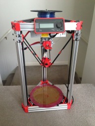
  1. jerry426

    jerry426 New
    Builder

    Joined:
    Feb 18, 2016
    Messages:
    68
    Likes Received:
    15
    Forgot to mention that I plan to offset the diagonal braces further from the frame using some sort of spacer - need to make sure I have enough clearance for the effector throughout the entire range of movement. I was anxious to get them included in the assembly to get a feel for how it looks. I will post updated images when I get the spacer figured out.
     
  2. jerry426

    jerry426 New
    Builder

    Joined:
    Feb 18, 2016
    Messages:
    68
    Likes Received:
    15
    ok.... I should have waited to post this spacer with the assembly - should give me enough clearance for the effector anywhere in the build area. After I get both the 20x20 end piece and this new spacer printed and verify proper fit, then I will post STL files for both. If you print this spacer, you will want to be 100% sure about layer adhesion for maximum strength. Now that I'm printing all my parts in PETG, I don't expect any trouble with it - but I can see it being a potential problem if you're using ABS and don't have it dialed in perfectly. Also note that I am printing everything at 100% infill - whereas I know many people are doing fine with 50 to 60% on these kind of parts.

    upload_2016-3-3_15-54-17.png
    upload_2016-3-3_15-54-55.png


    Front view:
    upload_2016-3-3_15-52-31.png
    Side view:
    upload_2016-3-3_15-53-22.png

    Rear upward view:
    upload_2016-3-3_15-51-43.png
     
    #572 jerry426, Mar 3, 2016
    Last edited: Mar 3, 2016
  3. jerry426

    jerry426 New
    Builder

    Joined:
    Feb 18, 2016
    Messages:
    68
    Likes Received:
    15
    More rigidity overkill - maybe too much? It's only an extra couple days of printing parts and a few $$ more in extrusion - so I'll probably do it. The "front" horizontal bar will be easily removed/replaced as needed for printed part access - probably being able to leave it attached 95% of the time.

    upload_2016-3-4_0-11-12.png

    upload_2016-3-4_0-12-10.png

    upload_2016-3-4_0-13-10.png

    upload_2016-3-4_0-15-19.png
     
  4. IrishHayZeus

    Builder

    Joined:
    Feb 25, 2016
    Messages:
    11
    Likes Received:
    0
    Jerry, keep in mind that the more joints you have connecting your braces, the more places that you're introducing flex into the overall design. I think your diagonal braces are probably beneficial, but I'm not sure about the mid-height horizontal, particularly with the standoff brackets.

    On another subject, are you using NEMA17 steppers in your vertex design? I've got 2 of my verticies printed, and placed what I thought was a NEMA17 stepper, but it doesn't match the mounting holes in the print (the motor mount points are smaller by about 2mm).
     
  5. lofton

    lofton New
    Builder

    Joined:
    Aug 13, 2015
    Messages:
    18
    Likes Received:
    2
    I'm curious about why you need so many braces. If it's because you think your extrusions are going to flex, then why not use 20x60 or 20x80 rails? I apologize if this is a dumb question. I have a tendency to over-build most of my creations and try to monitor myself for this.
     
  6. Thurmond Moore

    Builder

    Joined:
    Dec 31, 2014
    Messages:
    23
    Likes Received:
    4
    My take is "Plastic Flexes". Build all metal either with lost plastic metal casting or proper angled cuts and bolt metal to metal if flexing is an issue. IMHO! ;)

    Thurmond
     
  7. jerry426

    jerry426 New
    Builder

    Joined:
    Feb 18, 2016
    Messages:
    68
    Likes Received:
    15
    I pulled that NEMA17 pattern out of another part file I had.... let me double check that I did not somehow use the wrong pattern - but what you're saying has me worried that I screwed it up. Will check when I get home later!


  8. jerry426

    jerry426 New
    Builder

    Joined:
    Feb 18, 2016
    Messages:
    68
    Likes Received:
    15
  9. jerry426

    jerry426 New
    Builder

    Joined:
    Feb 18, 2016
    Messages:
    68
    Likes Received:
    15
    Curiosity may get me here regarding what, if any, improvements my added bracing will provide in terms of stiffness. I have a large welding jig table I can clamp the base of my printer to and plenty of ways to position dial indicators against the printer framework so I can watch the indicator needles move during machine movements. Perhaps I will do this - test with and without the extra braces to see how it flexes, twists, etc during various programmed movements. However, before any of that, I suppose I need to finish my build first! :)
     
  10. IrishHayZeus

    Builder

    Joined:
    Feb 25, 2016
    Messages:
    11
    Likes Received:
    0
    Cool. Thanks for checking on the motor mounts, Jerry. I'll track down another motor or two and see how they compare... its probably the motors I have are unique.

    I'm definitely curious how your tests go. I suppose the fact of the matter is, that anything to stiffen is better than nothing. So, you will probably find that they are in felt helping to reduce flex... but they may not reduce it enough to justify the trouble of the building the parts... except that you'll build the parts to test it. lol!
     
  11. DiggerJ

    DiggerJ Journeyman
    Builder

    Joined:
    Sep 2, 2014
    Messages:
    412
    Likes Received:
    109
    Wow! **** near kill yourself and miss a few months, and you guys have really been doing some great stuff with D6!

    Jerry426, your parts are beautiful, and look to be very functional. Don't let anyone dissuade on your attempts to stop the torsional twist in Deltas. It is one of the biggest problems that most neglect. The taller the printer the more you can see it. And if you put a couple of your last improvements (the horizontal bars tying the diagonals together), you have a really nice foundation for a heat enclosure frame!

     
  12. jerry426

    jerry426 New
    Builder

    Joined:
    Feb 18, 2016
    Messages:
    68
    Likes Received:
    15
    Thanks!

    Upon finding this Delta-6 build page I really liked a few things in the design so I decided to build one for myself and look for ways to make it better along the way. I have many 3D printers, but no delta so this is my first one - probably bigger than I should have started with. While cutting the extrusions for it this morning it became crystal clear to me that the drops from those cuts must be made into a little brother for this one - which means I now have 6 more vertexes to print.

    The few parts I had already printed for my new C-Bot CoreXY printer (before getting distracted with this build) are sitting in the corner in a box looking sad and neglected.

    Indeed, I will stay on course regarding frame stiffness improvements - even if some of the ideas don't yield as much benefit as I had hoped.

    Heat enclosure was always going to be something I considered last - attaching to wherever it makes sense - but your comment about it now has me thinking of ways to incorporate the heat enclosure into the frame enhancements.


  13. jerry426

    jerry426 New
    Builder

    Joined:
    Feb 18, 2016
    Messages:
    68
    Likes Received:
    15
    Progress!

    And now starting to print the diagonal brace parts. Looks like around 17 hours of printing for those 8 parts.

    upload_2016-3-5_19-45-18.png

    upload_2016-3-5_19-45-30.png
     
  14. AusCrash

    AusCrash New
    Builder

    Joined:
    Dec 27, 2015
    Messages:
    4
    Likes Received:
    1
    Looking good jerry!

    one thought I had when I started my build, based on metal garages when you put the sheets on it stiffens things up tremendously, was to enclose the frame with clear acrylic sides or similar. bolting on acrylic sides would make the whole thing rigid and have the added benefit of enclosing the space for better ABS printing.

    I still have that vague idea in my head, although no solid idea on how to actually implement it, leaving that until I get mine up & running and in use for a while. :)
     
  15. jerry426

    jerry426 New
    Builder

    Joined:
    Feb 18, 2016
    Messages:
    68
    Likes Received:
    15
    More progress - and 2 new STL files. I got the diagonal braces installed and found they make a very noticeable difference in rigidity as expected.

    Also uploading the STL files for the diagonal end piece and the frame mount.

    [​IMG]

    [​IMG]

    [​IMG]
     

    Attached Files:

  16. jerry426

    jerry426 New
    Builder

    Joined:
    Feb 18, 2016
    Messages:
    68
    Likes Received:
    15
    Carriage mounted belt tensioner:

    I was inspired by this one: Belt Tensioner/Clamp - Precision by rbilbrey

    With this finished, I will proceed with my final tweaks to the carriage, including bolt holes with captive nuts on the backside for this tensioner.

    upload_2016-3-10_1-1-13.png

    upload_2016-3-10_1-2-33.png

    upload_2016-3-10_1-3-34.png

    upload_2016-3-10_1-4-23.png
     
    #586 jerry426, Mar 10, 2016
    Last edited: Mar 11, 2016
    DiggerJ likes this.
  17. jerry426

    jerry426 New
    Builder

    Joined:
    Feb 18, 2016
    Messages:
    68
    Likes Received:
    15
    Here's the STL files for the belt tensioner assembly...
     

    Attached Files:

    Kyo and DiggerJ like this.
  18. David Bunch

    David Bunch Veteran
    Builder

    Joined:
    Oct 27, 2014
    Messages:
    622
    Likes Received:
    428
  19. IrishHayZeus

    Builder

    Joined:
    Feb 25, 2016
    Messages:
    11
    Likes Received:
    0
    Hey Jerry, it seems some of your images aren't coming through, and are referencing Google... Are you posting photos from Google Drive or something and failed to make them public? Some work, but some don't. Those that don't, consistently don't. Anyway, thought you might like to know.
     
  20. Kyo

    Kyo Veteran
    Staff Member Builder Resident Builder

    Joined:
    Feb 27, 2014
    Messages:
    673
    Likes Received:
    699
    Same here, I can review some of your photos posted but others are just greyed out.
     
  21. jerry426

    jerry426 New
    Builder

    Joined:
    Feb 18, 2016
    Messages:
    68
    Likes Received:
    15
    Trying again on the missing images...

    upload_2016-3-11_15-15-33.png

    upload_2016-3-11_15-16-2.png

    upload_2016-3-11_15-16-12.png
     
    Kyo likes this.
  22. IrishHayZeus

    Builder

    Joined:
    Feb 25, 2016
    Messages:
    11
    Likes Received:
    0
    Cool.. those come through. Thanks!
     
  23. jerry426

    jerry426 New
    Builder

    Joined:
    Feb 18, 2016
    Messages:
    68
    Likes Received:
    15
    My carriage and idler pulley design:

    The carriage has two pockets for a piece of 1/4" x 1/2" aluminum flat stock with holes drilled for the bolts (sized to match the holes in plastic). It makes the otherwise somewhat flexible plastic carriage very rigid to keep the wheels firmly in place in the v-slot. The two larger holes are for the OpenBuilds eccentric adjusters.

    My idler roller uses a pair of 625 bearings. The idler roller bracket simply sits in the top of the vertex with a snug fit so it cannot move - no screws hold it in place - which also made it easy to slide left/right as needed for perfect vertical belt alignment with the carriage-mounted belt tensioner.

    upload_2016-3-15_11-31-50.png
    upload_2016-3-15_11-35-25.png
    upload_2016-3-15_11-36-54.png

    upload_2016-3-15_11-37-25.png

    upload_2016-3-15_11-39-7.png

    upload_2016-3-15_11-39-57.png

    upload_2016-3-15_11-40-43.png

    upload_2016-3-15_11-42-42.png

    upload_2016-3-15_11-43-16.png

    upload_2016-3-15_11-43-43.png

    upload_2016-3-15_11-44-1.png
     
    Kyo likes this.
  24. jerry426

    jerry426 New
    Builder

    Joined:
    Feb 18, 2016
    Messages:
    68
    Likes Received:
    15
    Progress.... Motors, belts, carriages, rods, and Duet board installed. I made a pair of brackets to mount the Duet.

    My enclosure for the PanelDue is printing as I type this. I probably didn't need the PanelDue as I can use the web interface - but I decided it would look more finished with the LCD mounted.

    Next up is figuring out how I'll mount the end-stop switches. Then print the extruder parts, hot-end mounting and related items.

    upload_2016-3-18_21-43-46.png

    upload_2016-3-18_21-44-10.png

    upload_2016-3-18_21-44-24.png

    upload_2016-3-18_21-44-43.png

    upload_2016-3-18_21-44-59.png
     
  25. jerry426

    jerry426 New
    Builder

    Joined:
    Feb 18, 2016
    Messages:
    68
    Likes Received:
    15
    After not liking the direction I was heading with the PanelDue mounting I decided to do something easier while thinking more about mounting the PanelDue.

    End stop switch mounts:

    upload_2016-3-19_21-14-1.png

    upload_2016-3-19_21-14-52.png

    upload_2016-3-19_21-15-18.png
     
    Kyo likes this.
  26. jerry426

    jerry426 New
    Builder

    Joined:
    Feb 18, 2016
    Messages:
    68
    Likes Received:
    15
    It moves! Today I got the tower steppers and end-stops wired up along with mounting the PanelDue. After putting my critical dimensions from my CAD mockups into the config file, it keeps the effector perfectly level and at the same height everywhere in range of movement.

    I also printed some little plastic retainer clips which snap into the slot for holding wire down in the slot.

    My extruder parts are printing now. Still need to figure out exactly how I'm mounting the hot-end and fans on the effector.

    upload_2016-3-20_21-29-28.png

    upload_2016-3-20_21-30-0.png

    upload_2016-3-20_21-30-16.png

    upload_2016-3-20_21-30-36.png

    upload_2016-3-20_21-30-53.png

    upload_2016-3-20_21-31-13.png

    upload_2016-3-20_21-31-29.png
     
  27. IrishHayZeus

    Builder

    Joined:
    Feb 25, 2016
    Messages:
    11
    Likes Received:
    0
    Looking awesome, Jerry! If you get a chance, would you mind pulling together a zip of all your STLs?
     
  28. jerry426

    jerry426 New
    Builder

    Joined:
    Feb 18, 2016
    Messages:
    68
    Likes Received:
    15
    Yes, I will try to make a zip of them tonight or tomorrow along with many more progress photos.

     
  29. David Bunch

    David Bunch Veteran
    Builder

    Joined:
    Oct 27, 2014
    Messages:
    622
    Likes Received:
    428
    I liked the geometry of your diagonal brace frame mount.STL & decided to see how it would code parametrically in openscad and also cut down on the size of the STL file. Here is the openscad file & STL file.
     

    Attached Files:

  30. jerry426

    jerry426 New
    Builder

    Joined:
    Feb 18, 2016
    Messages:
    68
    Likes Received:
    15
    More progress photos for now. I need to clean up the mess of files in my modeling directory and then I will post a zip file containing all the STL files.

    upload_2016-3-27_0-49-29.png

    upload_2016-3-27_0-49-56.png

    upload_2016-3-27_0-50-14.png

    upload_2016-3-27_0-50-39.png

    upload_2016-3-27_0-51-9.png

    upload_2016-3-27_0-51-36.png

    upload_2016-3-27_0-52-22.png

    upload_2016-3-27_0-54-2.png
     

Share This Page

  1. This site uses cookies to help personalise content, tailor your experience and to keep you logged in if you register.
    By continuing to use this site, you are consenting to our use of cookies.
    Dismiss Notice