Welcome to Our Community

Some features disabled for guests. Register Today.

CNC xPRO Driver

Discussion in 'Other Builds' started by Spark Concepts, May 25, 2014.
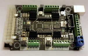
  1. gwandad

    gwandad Well-Known
    Builder

    Joined:
    May 12, 2014
    Messages:
    69
    Likes Received:
    55
    Just wire them across the switch terminals that you are using. one lead to each wire. Similar to these will do the trick. 10 Pcs 0.47uF Polyester Film Capacitor Radial Lead 63V
     
  2. snokid

    snokid Journeyman
    Builder

    Joined:
    Oct 11, 2014
    Messages:
    335
    Likes Received:
    104
     
  3. John Meikrantz

    John Meikrantz Well-Known
    Builder

    Joined:
    Nov 2, 2014
    Messages:
    169
    Likes Received:
    56
    The probe gets wired to A5, which is in the black connector on the xPro board.
     
  4. Firetruckguy

    Builder

    Joined:
    Aug 30, 2014
    Messages:
    23
    Likes Received:
    15
    image.jpeg

    I sort of got it working I can get it to move down and stop on the touch plate it won't raise up with the next command I put it on the back burner I'm working on getting my step mm accuracy on X Y Z
     
  5. azarock

    azarock New
    Builder

    Joined:
    Oct 11, 2015
    Messages:
    21
    Likes Received:
    5
    Correct, on the previous page Snokid posted a link to instructions. I have not done it yet, instead I just disabled the hard limits for now. In fact you could quickly do the same to verify that is indeed the problem. Just set $21=0, hard limits off.

    Here is what Snokid posted below my initial issue.
    CNC xPRO Driver | Page 15 | OpenBuilds

    Good luck.
     
  6. Rob Mitchell

    Rob Mitchell Well-Known
    Builder

    Joined:
    Nov 29, 2015
    Messages:
    105
    Likes Received:
    35
    Added the capacitors and homing now works, I get no alarms while homing.

    That being said I'm still getting alarms if I turn on hard limits!!! No idea what is going on there.

     
  7. Rob Mitchell

    Rob Mitchell Well-Known
    Builder

    Joined:
    Nov 29, 2015
    Messages:
    105
    Likes Received:
    35
    Another newbie question here.

    After homing the working tool (router) ends up bottom left corner with Z-axis raised. I assume from my high school geometry this location is x=0,y=0,z=X where X is some positive value to clear the work area.

    Why is is that my machine coordinates indicate negative values? I would have thought that bottom left corner after homing would be close to 0 if not zero and not some positive values.

    Is there a different cartesian coordinate system for GRBL or CNC in general? What am I missing?
     
  8. John Meikrantz

    John Meikrantz Well-Known
    Builder

    Joined:
    Nov 2, 2014
    Messages:
    169
    Likes Received:
    56
    Check the explanation on the grbl FAQ - Frequently Asked Questions · grbl/grbl Wiki · GitHub

    I had the same questions when I first started using homing.
     
  9. mcbuilder22

    Builder

    Joined:
    Jan 12, 2015
    Messages:
    45
    Likes Received:
    24
    I'm using a 12v 30a power supply with the CNC Xpro board and it's not providing enough power. If I have USB connected it has enough power but once that is disconnected the LED lights dim and it doesn't have enough power to function correctly. My use doesn't require or lend itself to have the USB always connected.

    Any suggestions? I've tried multiple power supplies to rule out a bad power supply.
     
  10. Firetruckguy

    Builder

    Joined:
    Aug 30, 2014
    Messages:
    23
    Likes Received:
    15

    I'm using a 24v 360w power supply, so far so good. NEMA 23 motors
     
  11. Rob Mitchell

    Rob Mitchell Well-Known
    Builder

    Joined:
    Nov 29, 2015
    Messages:
    105
    Likes Received:
    35
    Ok, I am getting the following error when trying to connect to board.

    "No supported kill alarm lock method for this version"

    This was after I hit the emergency stop button. Button is reset and power is running to motors. I try to connect using UGCS and it stalls at "Connected to xxxx ..." then waits a while then switches to "Connection closed ...".

    Even tried disconnecting the mains and connected to board just through USB but same result.

    Have I fried the board somehow?

    ***EDIT**

    Just went into UGCS > Settings > Firmware Settings > GRBL

    And it says "GRBL has not finished booting".

    What is going on?
     
    #461 Rob Mitchell, Jan 27, 2016
    Last edited: Jan 27, 2016
  12. John Meikrantz

    John Meikrantz Well-Known
    Builder

    Joined:
    Nov 2, 2014
    Messages:
    169
    Likes Received:
    56
    How are you using the xPro without being connected to the USB port?
    With the power supply plugged in are both the main power and 5v LEDs lit (on the USB end of the board)?
     
  13. mcbuilder22

    Builder

    Joined:
    Jan 12, 2015
    Messages:
    45
    Likes Received:
    24
    I'm using the Xpro as a custom Arduino based motor driver board to run multiple motors via push buttons. It's going to be inside a project with no need or access to USB.

    With the power supply plugged in the power and 5v LEDs do light up but they are half dim and the TX/RX and other LEDs do not light up. Once I plug in the USB the LEDs get brighter and then I see the other LEDs blinking and everything works as intended.

    Is this board not capable of running solely off a 12v 30a power supply? Would a 24v supply fix my issue?

    Thanks
     
  14. John Meikrantz

    John Meikrantz Well-Known
    Builder

    Joined:
    Nov 2, 2014
    Messages:
    169
    Likes Received:
    56
    That doesn't sound right. Maybe a problem with the board? Try contacting @Michael for feedback.
     
  15. Rob Mitchell

    Rob Mitchell Well-Known
    Builder

    Joined:
    Nov 29, 2015
    Messages:
    105
    Likes Received:
    35
    Hi @Michael (Mike), any chance you (or someone else here) can point me to the pinout assignment for the ISP pins on the board.

    Thanks


  16. mcbuilder22

    Builder

    Joined:
    Jan 12, 2015
    Messages:
    45
    Likes Received:
    24
    I just got a 24v 14.5a power supply and that seems to have fixed my issue. Thought I should post in case someone else stumbles upon this same issue. If you're using USB along with the board like it's original purpose the 12v supplies should be fine.
     
  17. John Meikrantz

    John Meikrantz Well-Known
    Builder

    Joined:
    Nov 2, 2014
    Messages:
    169
    Likes Received:
    56
  18. Rob Mitchell

    Rob Mitchell Well-Known
    Builder

    Joined:
    Nov 29, 2015
    Messages:
    105
    Likes Received:
    35
    When trying the print the DIN clip it is really small! Did you create this in metric or standard?

    Thanks

     
  19. Rob Mitchell

    Rob Mitchell Well-Known
    Builder

    Joined:
    Nov 29, 2015
    Messages:
    105
    Likes Received:
    35
    Anyone using a fan to cool the board? Which fan and specs? How did you wire it up and not run into a current draw problem?
     
  20. Catawissa_CNC

    Builder

    Joined:
    Aug 30, 2014
    Messages:
    12
    Likes Received:
    22
    This is metric
     
  21. Eric Schneider

    Builder

    Joined:
    Jan 10, 2016
    Messages:
    14
    Likes Received:
    0
  22. Rob Mitchell

    Rob Mitchell Well-Known
    Builder

    Joined:
    Nov 29, 2015
    Messages:
    105
    Likes Received:
    35
    Hi Eric,

    Can you explain a little more on what your intentions are. You control the steppers through GRBL code. Using various commands you can control the stepper motions. More information can be found on the GRBL wiki.

    Configuring Grbl v0.9 · grbl/grbl Wiki · GitHub


  23. Eric Schneider

    Builder

    Joined:
    Jan 10, 2016
    Messages:
    14
    Likes Received:
    0
    Originally I was hoping to control the steppers using the XPro board by programming it with Arduino code. The reason I wanted to do this was so that I could infrequently send waypoints from the computer to the XPro, and the XPro with my code on it would handle getting to those waypoints. I kind of wanted to play around with my own controls software instead of GCode. I thought that driving the motors would be something simple like just toggling the right ports. This isn't for a CNC machining tool, by the way, I'm trying to make a 2 axis drawing bot, doesn't need to be as precise as a machining device.

    When GRBL code is loaded on the XPro, how are the motors controlled? Do you send a number of steps to take? Or a pulse every time you want to take a step? Or do you send a distance to travel? How easy is it to vary motor speed dynamically?

    I'm very unfamiliar with GRBL, so thanks for your help. If I can set up the XPro to do what I want with the GRBL code on it that would be great.
     
  24. Rob Mitchell

    Rob Mitchell Well-Known
    Builder

    Joined:
    Nov 29, 2015
    Messages:
    105
    Likes Received:
    35
    Eric, I don't think you'll get much support for running anything other than GRBL here. This is what the board supports.

    The GRBL control language is very flexible. You can string commands together and "stream" them to the board. This is essentially what most control software does such as UniversalGCodeSender. You can control speed and the steps are very smooth with this board however there are many factors to consider which depend on your hardware setup and linkages. The simplest test is connecting a stepper up to one of the axis on the board, connecting the board to the Arduino IDE and running commands through Arduino IDE stream window.


  25. Eric Schneider

    Builder

    Joined:
    Jan 10, 2016
    Messages:
    14
    Likes Received:
    0
    Alright, it looks like I should look into streaming and play around with it a bit. I'll have to figure out the basic GRBL commands, which look a bit dense, but I'm sure I can find a lot of resources by googling. Thanks!
     
  26. snokid

    snokid Journeyman
    Builder

    Joined:
    Oct 11, 2014
    Messages:
    335
    Likes Received:
    104
    the cncxpro is a Arduino board paired with stepper driver chips. So you can do what you want.

    in Arduino code you have to include a 'Stepper' library then set the motor speed all you do then is send the number of steps and the direction to the chip and the motor moves.

    what grbl does is code that for you by using simple commands.

    Bob
     
  27. Eric Schneider

    Builder

    Joined:
    Jan 10, 2016
    Messages:
    14
    Likes Received:
    0
    Hi snokid, I was curious about that, thanks for the input. When I looked at the Arduino library it involved connecting the stepper to specific Arduino pins, like so:
    Stepper myStepper(stepsPerRevolution,8,9,10,11);
    From this file in the Stepper library: Arduino - StepperOneRevolution

    Do you know which pins should be referenced on the XPro board for which motors?
     
  28. Ronald van Arkel

    Staff Member Builder Resident Builder

    Joined:
    May 7, 2014
    Messages:
    472
    Likes Received:
    245
    The electronics are based on this:

    [​IMG]
    Limit switch pins have been changed and depend on what version of the xPRo you have.

    You might be better of using a separate motor driver and an Arduino (Uno) so it's easier to test signals.

    -Ronald
     
  29. Eric Schneider

    Builder

    Joined:
    Jan 10, 2016
    Messages:
    14
    Likes Received:
    0
    Hi Ronald, I saw that picture but didn't understand how it related to the Arduino Stepper library, which wants to be connected to four pins. The picture, in contrast, just has a single pin listed per axis. Do you know what the lines of Arduino code would be to drive a motor forward a step or change the speed?

    It still sounds like using the GRBL tools might be better, I just wanted to get a clear picture of what the Arduino-like options were, thank you.
     
  30. snokid

    snokid Journeyman
    Builder

    Joined:
    Oct 11, 2014
    Messages:
    335
    Likes Received:
    104
    first to answer your question the pinouts are right here....https://raw.githubusercontent.com/Spark-Concepts/xPRO/master/wiki/V2 xPRO pinout.jpg

    what you are trying to do (make a plotter) the cncxpro and a ox cnc would be somewhat overkill but the perfect setup. If you go to youtube and do a little searching a lot of people when they first get their cnc built tape a pen where the router would go and do a drawing.

    the workflow is pretty simple
    draw something you want to plot in cad software a lot of people including me use sketchup, it's free pretty easy to get up to speed up on.
    then you add the CAM plugin to sketchup sketchucam is another common plugin and also the one I use. for a plotter you would just enter the distance you want to pen to drop on to the paper instead of how deep to cut, really wouldn't be any other changes.

    the CAM part of this will generate g-code this is what you send the cncxpro. The xpro figures out what f200 x.090 means and moves the steppers to where they need to be.

    I get the feeling you are trying to do this on the cheap, not saying it can't be done, but a lot of times you end up spending more in the long run then if you just saved up a little and went another route....
    C-Beam Machine Mechanical Bundle
    if you look at what you get that's a pretty good deal. No figuring out does this fit do I need this, buying the wrong parts....etc....

    A lot of people will help even the greenest newbie get them going including me, feel free to p.m. me if you need help....
    long winded I know but I really like this stuff (just wish I had more time!!!)
    Bob
     

Share This Page

  1. This site uses cookies to help personalise content, tailor your experience and to keep you logged in if you register.
    By continuing to use this site, you are consenting to our use of cookies.
    Dismiss Notice