Welcome to Our Community

Some features disabled for guests. Register Today.

Cantilever Diode Laser Engraver V821

Discussion in 'Laser Cutters' started by David Bunch, Aug 17, 2021.
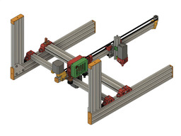
  1. David Bunch

    David Bunch Veteran
    Builder

    Joined:
    Oct 27, 2014
    Messages:
    622
    Likes Received:
    428
    I got the diameter down to 110mm & have a wrap around bracket for motor to use 2 motor holes. I added some 2mm holes spaced 1/2" apart so I could center object. Looks like this should work.
    TurnTable_V2.jpg
     
    Peter Van Der Walt likes this.
  2. David Bunch

    David Bunch Veteran
    Builder

    Joined:
    Oct 27, 2014
    Messages:
    622
    Likes Received:
    428
    I went about as minimal as possible using 608-2RS bearings. I was able to make it a lot shorter by mounting the motor below base, so everything rests on the bottom of motor. I got the diameter of the turntable down to 100mm. The 2mm holes on the top are actually spaced 1/4" apart & not 1/2".
    TurnTable_V3.jpg
     
  3. JustinTime

    JustinTime Veteran
    Builder

    Joined:
    Dec 18, 2013
    Messages:
    759
    Likes Received:
    253
    From your picture, David, the stepper looks like my NEMA 17 stepper which has the wires connected via a plug, like in the picture, that connects from the bottom and not from the side. That means you'll have to have the stepper on a platform to clear the connector.
     
  4. David Bunch

    David Bunch Veteran
    Builder

    Joined:
    Oct 27, 2014
    Messages:
    622
    Likes Received:
    428
    The connector on my stepper comes out the side & not the bottom, so I do not have any clearance problems as this picture shows.
    IMG_1453_800x600.jpg
     
  5. David Bunch

    David Bunch Veteran
    Builder

    Joined:
    Oct 27, 2014
    Messages:
    622
    Likes Received:
    428
    Here is a short video of the testing of this table. I might need a better way to center object on the turntable. I am going to reprint this table with concentric circles cut in & run a sharpie thru the grooves to see if that helps line it up easier. A manual centering chuck would be cool to have for this. I have a 72mm thick roll of painters tape I will use for my first burn test, then I can just peal off the layer after the test. I only had to make two changes in software to get it to work. I first set the grbl setting:
    $102=200.000 ;Z-axis steps per millimeter
    For the rotary setup in Lightburn I set mm per rotation to 32 which makes sense with the DRV8825 drivers. Lightburn uses the X-axis for the linear movement with the rotary setup, so I will have to swap the motor wires when running this.
     
  6. Peter Van Der Walt

    Peter Van Der Walt OpenBuilds Team
    Staff Member Moderator Builder Resident Builder

    Joined:
    Mar 1, 2017
    Messages:
    14,000
    Likes Received:
    4,112
    Mark Carew and Alex Chambers like this.
  7. David Bunch

    David Bunch Veteran
    Builder

    Joined:
    Oct 27, 2014
    Messages:
    622
    Likes Received:
    428
    Peter Van Der Walt likes this.
  8. David Bunch

    David Bunch Veteran
    Builder

    Joined:
    Oct 27, 2014
    Messages:
    622
    Likes Received:
    428
    I had a bit more troubleshooting to do with this turntable setup. Even though the rotary test worked, I could not get it to work with the Z-axis when doing a dry run of a burn rotary test. I tried swapping the 200 & 32 between Lightburn in the firmware & also tried 6400 & 1. I also set the enable Z-axis under Edit/Device Settings in Lightburn. After I moved the turntable axis to the Y-axis, it worked. Rather than having to change the:
    $101=160.000 ;Y-axis steps per millimeter to 200
    I changed the Lightburn mm per rotation to 40 which gives me a full revolution with 160 in firmware

    I probably should start a message on lightburn's forum & might get it to work on Z-axis.

    I printed 2 other turntable top ideas. The longworth chuck is pretty cool, but it only gives me 70mm diameter for this size turntable. Actually it could be a little more as I don't need those outside slotted holes & could extend the other arced holes further. I am going to use it like it for at least the first burn test since for the laser it might not be that critical to get it exactly centered.

    Here is what my 3 turntable top ideas.
    IMG_1457_800x600.jpg
     
    #38 David Bunch, Aug 23, 2021
    Last edited: Aug 23, 2021
    Peter Van Der Walt likes this.
  9. Mark Carew

    Mark Carew OpenBuilds Team
    Staff Member Moderator Builder Resident Builder

    Joined:
    Jun 28, 2013
    Messages:
    2,745
    Likes Received:
    2,410
    Good idea, I am sure they would love to hear the feedback.
    Coming along great David
     
  10. David Bunch

    David Bunch Veteran
    Builder

    Joined:
    Oct 27, 2014
    Messages:
    622
    Likes Received:
    428
    Here is the first burn test using the turntable.
     
  11. David Bunch

    David Bunch Veteran
    Builder

    Joined:
    Oct 27, 2014
    Messages:
    622
    Likes Received:
    428
  12. JustinTime

    JustinTime Veteran
    Builder

    Joined:
    Dec 18, 2013
    Messages:
    759
    Likes Received:
    253
    David, it's great that you've posted the Fusion and SketchUp files too. Most people don't do it. You can import .stl files into Fusion and Sketchup but it's a pain to make changes to them because of the triangles.

    Good show! :thumbsup: :thumbsup:
     
    Peter Van Der Walt likes this.
  13. David Bunch

    David Bunch Veteran
    Builder

    Joined:
    Oct 27, 2014
    Messages:
    622
    Likes Received:
    428
    Sometimes I release them, sometimes I don't. If you have the paid version of fusion 360, they made it a lot easier to convert .stl files to their format.

    I did get the Z-axis to work for the rotary today. It was probably a loose dupont connector in the JST plug. I put JST plugs on the 3 motor wires today, so that should not be an issue from now on.

    Someone thought the 2060s were kind of expensive, so thought I would make a bracket to use 2040s for feet. They are in Europe, so might be more over there. T-slots would also work for the feet with a slight modification to the bracket. I need that extra 20mm for the Z height of the laser, but someone could also use 2040s with it & put a piece of wood under it to the level they needed if they only wanted to use horizontal configuration. The 2060s feel like a good balance to me & machine is currently around 9lbs with everything attached. I designed a bracket to keep the same height as 2060 on the ends, but have not tested it yet. It is about an hour longer print for each one. Anyone have suggestions for this bracket?
    Ovhd_2040x2040Bracket.jpg
     
    Peter Van Der Walt likes this.
  14. David Bunch

    David Bunch Veteran
    Builder

    Joined:
    Oct 27, 2014
    Messages:
    622
    Likes Received:
    428
    I only had to loosen 3 Tee nut screws to take the 2020 cantilever off & it comes off as a whole assembly which I thought was pretty cool. Could have 2 assemblies, one short & one long. I took this apart to test fit a 1000mm 2020 on there. Seems like in the vertical configuration this extra length will work ok since the cantilever is pointing upward, at least it feels like it should work. I have some extra belt & might test it. I will have to make up a longer cable for the laser 1st. That should give me 705mm (27.75") burning height which is adequate to burn the top railing. Does that sound like it should work? If I cut some aluminum plates to replace the plastic ones, I bet it would be an even stronger connection. Is anyone interested in DXF files for the cutting the 2 main plates. I have them drawn up, but haven't uploaded them yet.
    IMG_1476_640x480.jpg
     
    Peter Van Der Walt likes this.
  15. David Bunch

    David Bunch Veteran
    Builder

    Joined:
    Oct 27, 2014
    Messages:
    622
    Likes Received:
    428
    I updated the Minimal_Rotary_Turntable_For_LaserEngraving.zip in the files area to include an Assembly guide for the turntable & 4 - M3x2mm spacers in case you want to use M3x10mm screws to attach a pancake motor. M3x10mm will probably work on deeper nema17 motors. The guide is mostly helpful to install the parts in the easiest order, at least for me. Here is an image of all the parts I used. I am hoping to test the longer vertical arm today.
    IMG_1464_640x480.jpg
     
  16. David Bunch

    David Bunch Veteran
    Builder

    Joined:
    Oct 27, 2014
    Messages:
    622
    Likes Received:
    428
    While playing with the long vertical axis between rain showers yesterday the difference in stability between 600mm & 1000mm 2020 is noticeable on the vertical cantilever, but dry run at the slow speed this runs seems like it will work. I did not get a chance to do a burn test because of the off & on rain.

    Anyway, this got me to thinking of using 2 - 2020s in the back instead of the 1 - 2040. Print times will not be that much longer. In the middle of the night I had to get up & put this assembly together to see how it looks. The top plate is duplicated for the back 2020 & the front Tee slot connection is matched with the back M5 hole on the bottom plate. There are 4 extra wheel assemblies & 4 extra Tee Nuts with screws on each end & one extra Tee Nut & screw on back of the 2nd top plate.
    V821_2020_Vertical_Assembly.jpg
     
    Peter Van Der Walt likes this.
  17. David Bunch

    David Bunch Veteran
    Builder

    Joined:
    Oct 27, 2014
    Messages:
    622
    Likes Received:
    428
    One of my biggest problems with using this laser outside for me is blocking the light in direction where people might see it. In the vertical configuration I realized I could 3d print a disc & will block most of the light from that direction. It is not really any weight on the carriage in that orientation. Am printing it now to see if it blocks a wide enough area for my situation. You could also use a paper plate & cut a tight fitting 2020 square hole in it & tape it to 2020 z-axis if necessary. This part is 200mm in diameter & paper plate I have is 255mm.
    LE_VerticalLightShield.jpg
    I also have enough parts to test the double 2020 beam except I will use 2040 for the 1st beam since I do not have 2 - 2020s of the 600mm length I want. Using the double 2020s is currently 110.25mm total width & has same work area as before. With the 2040 for front beam, I loose 20mm, but I can probably adjust the cantilever forward 20mm for that as there is a lot more support for it this way. I broke down the cost of this new style & it could be less than $20 more depending on the source of your parts.
     
    Peter Van Der Walt likes this.
  18. JustinTime

    JustinTime Veteran
    Builder

    Joined:
    Dec 18, 2013
    Messages:
    759
    Likes Received:
    253
    Or tap the center hole in the 2020 and screw the plate to the 2020. :)
     
  19. David Bunch

    David Bunch Veteran
    Builder

    Joined:
    Oct 27, 2014
    Messages:
    622
    Likes Received:
    428
    Thanks. That would certainly make the pie plate easier to attach. I will have to try that. It would also cut out the plastic mount on the printed part. I was trying to keep from having to tap extrusions. I am ok with doing myself now, but there are probably a lot of folks that are not comfortable with doing that. After I found Rick's method of drilling it out the 3/16" & threading a long M5 screw in, I have not had any problems since. I have tried a couple of taps, but haven't gotten the hang of that yet.
     
  20. David Bunch

    David Bunch Veteran
    Builder

    Joined:
    Oct 27, 2014
    Messages:
    622
    Likes Received:
    428
    Thank you JustinTime for the simple method of using screw hole for the plate. That worked really well as you can see in this video of engraving a 350mm along the top rail on my deck.
     
    Peter Van Der Walt likes this.
  21. David Bunch

    David Bunch Veteran
    Builder

    Joined:
    Oct 27, 2014
    Messages:
    622
    Likes Received:
    428
    This looks like the best choice self centering clamp I have found to make work with the turntable. I cam easily make it go from 1.5" to 5" diameter, but need it to be about 5.5" for a bamboo utensil holder. I will probably put a set screw of some sort in one of the legs to hold it once it is centered.
    Slot Cam & four Slider Follower Mechanism | 3D CAD Model Library | GrabCAD

    Here is the youtube video he made on how to design this.
    How to design a Slot Cam & four sliding follower mechanism in Autodesk Fusion 360 - YouTube
     
  22. JustinTime

    JustinTime Veteran
    Builder

    Joined:
    Dec 18, 2013
    Messages:
    759
    Likes Received:
    253
    David, he posted the f3d file which is a Fusion360 file. With it you can easily change it to any size you want. I may take longer to load it to your computer than it will take to make it bigger! :) :)

    BTW, if you are not familiar/working with Fusion360 I can upload the .stl file with the bigger plate for you.
     
    #52 JustinTime, Aug 29, 2021
    Last edited: Aug 29, 2021
  23. David Bunch

    David Bunch Veteran
    Builder

    Joined:
    Oct 27, 2014
    Messages:
    622
    Likes Received:
    428
    Thanks, I downloaded just before uploading that message, modified the fusion 360 file & now just starting the print. I will probably have to change it some more, but will see how it works.
     
  24. David Bunch

    David Bunch Veteran
    Builder

    Joined:
    Oct 27, 2014
    Messages:
    622
    Likes Received:
    428
    This is what I came up with for first attempt. It has a 3d printed bearing with a wheel bearing & washer at the bottom. The plastic bearing rests on the motor. Not sure I need the washer & wheel bearing since that bearing should not be turning. Also not sure how well the plastic bearing will print, but I put the tolerances in that work for me & drew it from scratch in Fusion 360. It has 17 bearings 8mm in diameter. I have a M5 hole with nuttrap for M5 locknut to secure 1 - 4 of the sliders once diameter is set. The other parts are just modified from version on grabcad.
    TurnTable_SlideCam.jpg TurnTable_SlideCam_Section.jpg
     
    Peter Van Der Walt likes this.
  25. David Bunch

    David Bunch Veteran
    Builder

    Joined:
    Oct 27, 2014
    Messages:
    622
    Likes Received:
    428
    This came out reasonably well for a first try. The bearing print had a layer shift, so I made a simple plate that just slides against plastic base and threads into the motor. Seems ok when manually moving it. It has room for improvement. I did find that all 4 sliders will need to be locked once it is set, so I have redrawn it to use only 3 sliders and cut out some plastic where I could. I also made the base center opening round to center it on bearing plate. The top turntable does not need to be circular to hold the item so cut out a considerable amount of plastic. I did make it 4mm thick where I had it 2mm thick before.
    IMG_1494_800x600.jpg IMG_1495_800x600.jpg IMG_1496_800x600.jpg Longworth3PinClamp.jpg
     
  26. David Bunch

    David Bunch Veteran
    Builder

    Joined:
    Oct 27, 2014
    Messages:
    622
    Likes Received:
    428
    I found a couple of problems with this new version. 1st off, I have no room to tighten the bracket for the top turntable to the motor. After looking at the assembly, I can put the bearing bracket upside down from the way I intended & I can get to that bracket screw if I lengthen the bracket by 10mm. I also printed the sliders shorter this time so they did not stick out so far, but realized they need to be that long when I use the M5 screw & locknuts to press against them. I am not crazy about that solution to holding the sliders in place, but haven't come up with another solution. For the shaft connection, I maybe able to make it longer & raise the gap between bearing base turntable slider base. Here are photo progress. I forgot to put the 3-M5x12mm screws & locknuts in the parts photo. The 3 sliders do slide better than the 4 sliders.
    IMG_1497_800x600.jpg IMG_1500_800x600.jpg IMG_1502_800x600.jpg
     
    Peter Van Der Walt likes this.
  27. David Bunch

    David Bunch Veteran
    Builder

    Joined:
    Oct 27, 2014
    Messages:
    622
    Likes Received:
    428
    My current thought is there should be a way to use a servo to automatically center these objects, then the servo could hold them in place. Anyone have another idea along these lines? Maybe I can make it like the longworth clamp that Peter Van Der Walt mentioned earlier with another top going the opposite way & control that with a servo some how. After some further thought while writing this, think I can have longer pegs, mount the servo to bottom slotted top & rotate a top slotted top with servo. Servo can actually be recessed below the bottom top since there is plenty of room with the long bracket & top top can sit flush on bottom top. That seems like it should work. Here is the idea that sparked that thought.
     
    #57 David Bunch, Aug 31, 2021
    Last edited: Aug 31, 2021
    Peter Van Der Walt likes this.
  28. Peter Van Der Walt

    Peter Van Der Walt OpenBuilds Team
    Staff Member Moderator Builder Resident Builder

    Joined:
    Mar 1, 2017
    Messages:
    14,000
    Likes Received:
    4,112
    As Grbl's PWM output is used for the laser, it would be hard (no spare timers for Servo without - if even possible - modifications to firmware)

    But a coolant output is still spare, on/off though, no PWM. Maybe solenoid or DC motor
     
  29. David Bunch

    David Bunch Veteran
    Builder

    Joined:
    Oct 27, 2014
    Messages:
    622
    Likes Received:
    428
    That being the case, a 28BYJ-48 or use the pancake motor for that & a larger motor at the base. The motor would be easier to move in steps rather than the servo anyway. I have 3 stepper drivers on that board & only 2 are needed for the rotary axis. I can just swap the cables when using the turntable. I know there is a mod to change the 28BYJ-48 from unipolar to bipolar if I need to.
     
  30. David Bunch

    David Bunch Veteran
    Builder

    Joined:
    Oct 27, 2014
    Messages:
    622
    Likes Received:
    428
    A motorized aperture like this might also be a good possibility. I saw this before, but discounted it because the apertures come out a ways at full open. If I set the minimum diameter to 1-1.5" it might be reasonable.
    120mm Fan Apenture/Iris Cover by Axaroz
     

Share This Page

  1. This site uses cookies to help personalise content, tailor your experience and to keep you logged in if you register.
    By continuing to use this site, you are consenting to our use of cookies.
    Dismiss Notice