Welcome to Our Community

Some features disabled for guests. Register Today.

LEAD 1515, HGH15, SFU1604 Ball Screw

Discussion in 'CNC Mills/Routers' started by Netechsys, Sep 7, 2020.
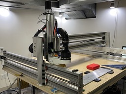
  1. JustinTime

    JustinTime Veteran
    Builder

    Joined:
    Dec 18, 2013
    Messages:
    759
    Likes Received:
    253
    I have the 16mm ball screws and they whip if I go fast. They are 1500mm and 1400mm.

    I bought some thrust bearings and I'm looking for ideas on how to make the mounts.
     
  2. Rob Taylor

    Rob Taylor Master
    Builder

    Joined:
    Dec 15, 2013
    Messages:
    1,470
    Likes Received:
    746
    How fast? Fixed-free 1500mm screws should whip at 700rpm. That's 3500mm/min on 1605s. If it's below that, and they're fixed-supported, there may be some other problem like a misalignment. If it's around 5000mm/min, then yeah, you're in the ballpark for whip anyway.

    Here's an idea I literally just came up with whilst typing this for tensioning a screw without a complex moving-bracket assembly with spring washers. Using a parallel-thread hollow screw or drilled-out plug (eg. hydraulic) with a matching flange (eg matching 1" BSPP plug and flange), mount the flange to your end plate, screw the hollow screw all the way in, put the end of your screw through the flange and screw, add the thrust bearing and clip on the circlip. Then simply unscrew the screw. Et voila! Instant tension. If I hadn't already cut all my plates and CAMed them, I might consider doing it myself.

    Admittedly, this gets ten times easier if you have access to a lathe so you're not so limited in terms of through-bore options and can just drill your own hole, but I think it's doable basically without any tools if the right components can be found.
     
  3. Peter Van Der Walt

    Peter Van Der Walt OpenBuilds Team
    Staff Member Moderator Builder Resident Builder

    Joined:
    Mar 1, 2017
    Messages:
    14,001
    Likes Received:
    4,113
    In 2014 i built a couple machines where we had the ballscrews turned down to 8mm * 6mm length on the end, with a M6 center bore. Didnt use it as tension system, only to locate the end of the ballscrew in a bearing. But if i understand the above correctly, there's an idea there in too, added to my personal build notes for sure, if i ever revisit that design, do the same at the other end, pull tension in with the bored thread.

    Pics below of Z axis, couldnt find pics of machined ballscrew or other axes on a quick search.

    FB_IMG_1610898396120.jpg

    FB_IMG_1610898411115.jpg
     
    #93 Peter Van Der Walt, Jan 17, 2021
    Last edited: Jan 17, 2021
    sharmstr and JustinTime like this.
  4. Rob Taylor

    Rob Taylor Master
    Builder

    Joined:
    Dec 15, 2013
    Messages:
    1,470
    Likes Received:
    746
    That was actually the first variant of the idea that popped into my head! But obviously you'd need the screw machined accordingly already, so I went to the "hollow surround" option. But yeah, center screw would allow for very precise shim-based tension setting, definitely a good idea to hold onto.
     
    Peter Van Der Walt likes this.
  5. Netechsys

    Netechsys Journeyman
    Builder

    Joined:
    Mar 25, 2020
    Messages:
    149
    Likes Received:
    107
    Now. That’s a nice way to tension a ball screw. Next machine specs are changing by the day. This is why I love and hate this site. LOL

    next machine will be a mini mill that won’t be so mini. Between a C-Beam and mini mill. Well. That’s the thinking now.
     
    sharmstr and Peter Van Der Walt like this.
  6. Netechsys

    Netechsys Journeyman
    Builder

    Joined:
    Mar 25, 2020
    Messages:
    149
    Likes Received:
    107
    Ok. So this is a thick bracket. This is the X free floating end plate. It will attach the c-beams to the uprights. Need to drill the through holes how. 20mm thick.
    443AEF1E-EAAB-4225-AA0F-DF1BFA675F03.jpeg
    299B4E67-EE43-40D1-B7F3-27A874B2C634.jpeg
     
    #96 Netechsys, Jan 19, 2021
    Last edited: Jan 20, 2021
  7. ljvb

    ljvb Well-Known
    Builder

    Joined:
    Feb 14, 2019
    Messages:
    276
    Likes Received:
    87
    I like openbuilds.. but I don't think the mini mill is worth it. If you order a complete setup (steppers, controler, etc etc), you are looking at around 1100ish... And that is before you start spending on upgrades and modifications...

    At that point, you may as well get an actual mill, the Grizzly g0704, of even the Precission Mathews PM25.. and then modifying/upgrading to an CNC. Yes you are looking at $2k to $2.5k all in, but you will get an actual mill that can mill pretty much any material, as well as using the larger milling tools.. rather than being limited to 1/4 bits..
     
  8. Netechsys

    Netechsys Journeyman
    Builder

    Joined:
    Mar 25, 2020
    Messages:
    149
    Likes Received:
    107
    Last plates completed tonight. Did a mock up to make sure everything worked as designed, and I’m very happy with the end results. This is the X plates. I moved the X axis back 10mm to remove some of the overhang off the front of the system.

    9A04D3A6-CEEE-4868-A7AC-46AEE4BAE789.jpeg

    Now, no angle brackets are needed, and the entire bracket becomes the connection, so 220mm to keep everything square. Total size for these plates are 220x70. The holes behind the c-beams that have nothing in then are to attach the 2040 across the back for the cable tray.

    next on the hit list is to make the Z axis over, and beef it up. Any recommendations on how to do it? Travel is 200mm. I think I may just mill aluminum braces to attach to the outside of the C-beam for the z axis, but I’m not against making it completely from scratch.

    X axis attached tonight with the new plates. Here is the floating side attached.
    5D2F1698-0BD2-4012-B315-E864A920D3EA.jpeg
     

    Attached Files:

    #98 Netechsys, Jan 22, 2021
    Last edited: Jan 24, 2021
  9. Netechsys

    Netechsys Journeyman
    Builder

    Joined:
    Mar 25, 2020
    Messages:
    149
    Likes Received:
    107
    Rebuilt the y/x/a axis to install new plates and retram entire machine. Everything bolted right up and square, so I’m quite happy. Now on to the z axis. The aluminum on the machine is for that.

    will be tackling the z axis tonight/tomorrow, so hopefully be completed by weekend. Using the design cues from a few other builds to customize the Z, and hopefully will work. More to come.

    Machine 2 parts on order. C-beam XL with linear rails and ball screws. I’m also ordering closed loop steppers for this one, but will probable swap them around when then get here and use the open loop steppers from this machine on the new one.
     

    Attached Files:

  10. Netechsys

    Netechsys Journeyman
    Builder

    Joined:
    Mar 25, 2020
    Messages:
    149
    Likes Received:
    107
    Draft 1 of the Z-Axis update.

    Screen Shot 2021-01-29 at 3.58.18 PM.png

    Linear rails will be fixed to the back of the base plate. The back braces will protect the linear blocks and the rail to help eliminate any chips from getting to them and add rigidity. This will move the spindle back 45MM to allow for complete use of the spoil board. This should push the 0/0 location just onto the spoil board, and eliminate any overhang. The entire axis will be fix together with M6 cap screws from the back to the front making this one unit. The spindle mount is a solid mount, 85MM wide, so the entire area that is open will be where the spindle mount attaches, and will be sandwiched between the from and back supports.

    Still working on the back side for the ball screw attachment, but I am thinking about eliminating the nut block and using the flange on the ball nut to attach to the Z-Axis. Trying to make the distance between the X plate and the Z plate as narrow as possible, Not sure yet. But this is the basic design..

    attaching a photo of the Z axis is process. Back plate profile and cut out for the spindle mount done. 2E7613CA-8C63-4073-B579-3EFFDEA2A039.jpeg
     
    #100 Netechsys, Jan 29, 2021
    Last edited: Jan 29, 2021
  11. Netechsys

    Netechsys Journeyman
    Builder

    Joined:
    Mar 25, 2020
    Messages:
    149
    Likes Received:
    107
    New z axis shaping up. I changed the front struts, and went flat. I’ll look at adding struts on the front if I get flex, but I think this will help a lot. Basic structure is 3/8 plate for the middle, 1/2” off the front, and 3/4” off the back creating an I-beam. All held together with m8 bolts.

    will have to re-design the dust collection as there isn’t enough space between the spindle and the back plate now. There is about .5mm between now.

    1CB1766F-B7AC-40FD-A835-392A461FA6EF.jpeg

    Total, this will move the spindle back about 32mm. This will help keep everything on the spoiler board in the frame.

    Also added simple brackets to the front and back of the C-beams of the Y/A to attach more
    Solid to the flame and eliminate the cast angle brackets. A project later will be to make these as one piece. (Thanks @Rob Taylor for the idea after looking at M4 again.)

    image.jpg

    Last project for this is side shields for the inside of the Y/A C-beams. A simple 1/4”x10” aluminum bar, milled to the exact 220 dimensions to close off the sides. And then this will be a wrap! Well, except for the enclosure, but that’s another story.

    All in all. Quite happy with the outcome. I’m now making my own aluminum parts and ready to make the next machine.
     
  12. Rob Taylor

    Rob Taylor Master
    Builder

    Joined:
    Dec 15, 2013
    Messages:
    1,470
    Likes Received:
    746
    Looks like this Z's coming along nicely! Good to keep that gantry overhang distance so small.

    Getting ready to start painting my steel screw mounts/rail caps today. I do have cast brackets between the base frame "branches" and the lower C-Beam on each side of the Y-axis, just not showing- only underneath. Should be strong enough, especially once I bracket the base frame directly to the bench.
     
    Mark Carew likes this.
  13. Netechsys

    Netechsys Journeyman
    Builder

    Joined:
    Mar 25, 2020
    Messages:
    149
    Likes Received:
    107
    Wow. Quick delivery. Aluminum for last few projects already arrived. Just placed the order yesterday!

    1EDE62F3-5622-43E3-A0DB-6134FD3F96DA.jpeg

    Cant tell in the pic. But 1/4x10x60 inches is a big piece of aluminum.

    hopefully will finish up the Z and this parts this weekend!
     
    Mark Carew likes this.
  14. Mark Carew

    Mark Carew OpenBuilds Team
    Staff Member Moderator Builder Resident Builder

    Joined:
    Jun 28, 2013
    Messages:
    2,745
    Likes Received:
    2,410
    This build is moving right along an looking very nice. Great job @Netechsys for sure a beast of a machine :thumbsup:
     
  15. Netechsys

    Netechsys Journeyman
    Builder

    Joined:
    Mar 25, 2020
    Messages:
    149
    Likes Received:
    107
    Tonight, decided to hook the interface up to the system, and use it instead of the PC. Have to say, quite impressed with it so far. Ran 7 jobs with it, uploading the g-code from the web portal, and all worked. And was very easy to use.

    Openbuilds team outdid themself with this addition! Even with out using their controller anymore, still work great!
     
    Peter Van Der Walt likes this.
  16. cnc0014

    cnc0014 New
    Builder

    Joined:
    Nov 29, 2020
    Messages:
    11
    Likes Received:
    3
    Do you get much flex at the bit? I have a stock build and when the z axis is centered on the x I can flex the c beams a lot. I just bought a scale to pull on the bit with a consistent poundage and will set my dial indicator up to quantify the movement but at this point it is moving an unacceptable amount. Wondering if the linear rails you mounted in the C channel stiffens the beams up. I am likely going to run steel channel in the c beam like this person did:
     
  17. Netechsys

    Netechsys Journeyman
    Builder

    Joined:
    Mar 25, 2020
    Messages:
    149
    Likes Received:
    107
    with the Linear rails, and the end mounts I made, the system really stiffened up. Here is a quick cut, 8.5mm doc, 1500mm/m, 18k RPM with a 1/4” end mill cutting 3/4” MDF for the new spoiler board setup. As you can tell, there is no problem at that rate.

    and, after I mount the new Z axis later today, it will stiffen up even more.
     

    Attached Files:

    #107 Netechsys, Feb 7, 2021
    Last edited: Feb 7, 2021
  18. Netechsys

    Netechsys Journeyman
    Builder

    Joined:
    Mar 25, 2020
    Messages:
    149
    Likes Received:
    107
    New spoiler board going on. Adding t-rail between boards and 1/4” bolt down points through out.

    4DD4A3AE-6BEA-4F3B-B78E-A2466CD5DEAB.jpeg
    top layer will have a grid etched into the top for alignment.

    image.jpg

    between layers of the spoiler board there will be t-nuts embedded into the board.
     
  19. cnc0014

    cnc0014 New
    Builder

    Joined:
    Nov 29, 2020
    Messages:
    11
    Likes Received:
    3
    I put a sheet of baltic birch down and used drop in T nuts to hold that down to the slots in the aluminum. Then I screwed these down to the baltic birch with 165mm wide 3/4" MDF strips held down to the baltic birch with threaded inserts in the baltic birch. I want to do popup reference pins but I am working on a design. I figured it would be easy to source a delrin or aluminum pin that is a plunger that locks down and pops up. No luck. Going to drill 20mm holds in the vertical with a couple t tracks but I am chasing either an EMI issue or something else along with an unacceptable amount of flex at the bit. I am on the verge of just selling it and getting something else because I am not interested in spending more time and money on this. We will see. A Stepcraft or something similar may be in my future if I can't figure this out.

    IMG_2148.jpeg
     
    Netechsys likes this.
  20. Netechsys

    Netechsys Journeyman
    Builder

    Joined:
    Mar 25, 2020
    Messages:
    149
    Likes Received:
    107
    Nice looking machine. I like the setup.
    Here it is completed. Will run the SB surfacing tomorrow.

    FE14D349-7523-4D0F-AFAE-14DB95BFD7D5.jpeg
     
  21. SenseiFranks

    Builder

    Joined:
    Oct 31, 2018
    Messages:
    3
    Likes Received:
    0
    Have the double y c-beams helped with more stability? I just got my 1515 put together, and have the needed parts to swap out for the high z mod, but I can already see a potential for a lot of flex if I put the extrusions on. I am also looking into a custom double end plate to tie additional c-beams on each side, except running it just like the x axis is so I don't have to swap out even more stuff. I have yet to find anything already made, so I am hoping I can use my machine like it is to cut our 4 aluminum plates for the y axis, and maybe 2 for the x just to tie those in more evenly.
     
  22. Netechsys

    Netechsys Journeyman
    Builder

    Joined:
    Mar 25, 2020
    Messages:
    149
    Likes Received:
    107
    Yes, it helped some. The linear rails help a lot. And the new end plates helped tremendously. With the double C-beam, getting the tram and parallel of the 4 linear rails took time, and after the new plates, was much easier.

    Now that I’m done, there are a few changes I would make, like how I mounted the linear rails for one. (Looks, not functionality. ). But, I can’t complain on the travel I am getting, and the rigidity.
     
    SenseiFranks likes this.
  23. Netechsys

    Netechsys Journeyman
    Builder

    Joined:
    Mar 25, 2020
    Messages:
    149
    Likes Received:
    107
    Was getting some wavy readings from the spoiler board. I have a 3/4” Baltic Birch screw through to the torsion box below the frame. With a 3/4” MDF middle, and a 1/2” MDF top. Was getting about .5-.8mm variation from end to middle. And then back to within .1 at the far end. So decided to beef up the spoiler board, since I beefed up the rest of the machine.

    solution? Let’s turn the machine base into a torsion box. So. Baltic birch torsion box on the bottom, an aluminum torsion box on the middle, and then the spoiler board on top. I’ll take measurements and report the results, but it’s gotta be better!

    E1C2BC37-9A78-40ED-AE7A-744A8A08A5C4.jpeg

    Cross supports every 300mm along the length of the frame. 12 500mm 2040’s. And some angle connectors.
     
    SenseiFranks likes this.
  24. Netechsys

    Netechsys Journeyman
    Builder

    Joined:
    Mar 25, 2020
    Messages:
    149
    Likes Received:
    107
    Quick update. Where I was getting .6-.8mm prior to the supports, now it’s about .15-.2 after. So much better. Once I change the Z axis, I’ll surface the spoiler boards to take that all out. But, it is much stiffer now.

    Tonight, added a new dust collector system to the machine. Replaced the wet/dry vac with a 2hp 2 stage dust collector. Installed the dust collector in the garage, and ran a 4” line in to the cyclone I installed under the machine. And I’m adding a sweep port by the front of the machine to ease floor clean ups.

    FF45B60C-5417-4A93-B925-713229D79F29.jpeg

    Line ready for hook up tomorrow, as I ran out of 4” hose. Need another segment. All controlled by the coolant IoT’s.

    Tomorrow, starting to mill the side panels to finish up the machine. Also changing the ball screws to sfu1610’s from the 1604’s and having them custom machined so they will be fixed on both ends. (Thanks to @Rob Taylor for the assist with being a sounding board for ideas!). So, I have the ball screw now for the Lead Lathe I’m looking to build, based off of @Giarc design.

    almost to the completed end.
     
  25. Netechsys

    Netechsys Journeyman
    Builder

    Joined:
    Mar 25, 2020
    Messages:
    149
    Likes Received:
    107
    Well. ****. Was starting the aluminum tonight for the side panels. I was going to put a angle on top, 1/4x2, milled to cover the top of the c-beam and become the base platform for the 1/4 plate to cover the inside. I was also adding a 1/4x1” on the bottom c-beam so it was all nice and level. Only problem is I though I ordered 6063 angle, which gives a nice 90 degree corner inside and out. But, I got 6061 angle which has a nice radius on the inside corner. Now it won’t sit right. Do I attempt to run an endmill down the length of the angle to clear it out, and then reposition it to clear out the other end. (1524mm long and y axis has 1370mm travel.)

    great plan. Poor execution

    Well. Put this aside for now. Finish the Z axis instead.

    I’m open for suggestions.
     
  26. Peter Van Der Walt

    Peter Van Der Walt OpenBuilds Team
    Staff Member Moderator Builder Resident Builder

    Joined:
    Mar 1, 2017
    Messages:
    14,001
    Likes Received:
    4,113
    I'd bevel whatever it has to sit against. Should be easier?
     
  27. Netechsys

    Netechsys Journeyman
    Builder

    Joined:
    Mar 25, 2020
    Messages:
    149
    Likes Received:
    107
    it’s going against the C-beam. To bevel the c-beam, I would have to disassemble the Y/A/X. I’ll look at that in the morning. It’s too late. And I’m about ready to take a hacksaw to it.
     
    Peter Van Der Walt likes this.
  28. Giarc

    Giarc OpenBuilds Team
    Staff Member Moderator Builder Resident Builder

    Joined:
    Jan 24, 2015
    Messages:
    2,916
    Likes Received:
    1,619
    I found on my build that the radiused angle is not quite 90 degrees either.
     
    #118 Giarc, Feb 16, 2021
    Last edited: Feb 16, 2021
  29. Netechsys

    Netechsys Journeyman
    Builder

    Joined:
    Mar 25, 2020
    Messages:
    149
    Likes Received:
    107
    “But, these little set-backs are just what we need to take a giant step forward. Needless to say, I was a little despondent about the melt down, but then, in the midst of my preparations for hari kiri, it came to me.”

    why not use my palm router with a top bearing pattern bit to clean up the inside radius.

    B31D412F-78D2-41E2-A771-88C2F3DC59CA.jpeg

    Same 6061 angle corner. Top, not cleaned up. Bottom, cleaned up. Took about 1 min to do it.

    image.jpg

    That will do!
     
  30. Netechsys

    Netechsys Journeyman
    Builder

    Joined:
    Mar 25, 2020
    Messages:
    149
    Likes Received:
    107
    Ok. Let’s try a big file with the interface. Still uploading then I’ll run it.
    CB6BFE4A-E0DB-422A-AE87-8472C82501CF.jpeg
     

Share This Page

  1. This site uses cookies to help personalise content, tailor your experience and to keep you logged in if you register.
    By continuing to use this site, you are consenting to our use of cookies.
    Dismiss Notice