Welcome to Our Community

Some features disabled for guests. Register Today.

A Rolling Plotter

Discussion in 'DrawBot' started by David Bunch, Feb 21, 2020.
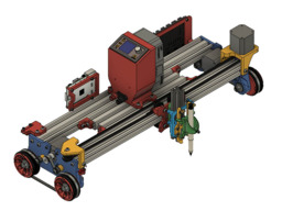
  1. David Bunch

    David Bunch Veteran
    Builder

    Joined:
    Oct 27, 2014
    Messages:
    622
    Likes Received:
    428
    I got the bright idea yesterday to shorten the 3d printed TPU belt by 8mm since it stretches a little & the 2nd test print using it worked the best so far. I found the F695zz flange bearings of the bearings I had worked the best for these idler pulleys. I can tighten the screws all the way down & they still turn nicely. I have 8 of those bearings used now, 2 for each idler. I had a loose grub screw on one the wheel motors which was probably causing part of my problem before. It is still not perfect, but I didn't see any missed steps this time. I am really liking using the klipper firmware with this machine. There is also a octoprint plugin called octoKlipper that adds a little more flexibility to it like adding button macros for specific code. Here are the buttons I made so far.
    OctoKlipper_Macros.jpg

    Think I figured out a way to get the correct inner ring gear draw correctly with this Ferris Wheel or I like the term Jeff on v1engineering used for it, a Hamster wheel. I created the drive gear & inner ring with openscad using Gear Bearing by emmett I then merged that with a 44T double Helical gear for the outer ring which is 105mm outer diameter. I will probably have to use 2 or 3 bearings rolling along the flat part of the ring to keep it from wobbling, but will just print it for now to see how it meshes. Might have to create some sort of tunnel for it also so it doesn't wobble the other way, but 1st things 1st. Looks like that big ring is going to be a 2 hour print. I was thinking I could put a idler bearing gear on those end V-slot connections, but the distance is too short to get a gear in there with the current specs I am using.
    HamsterWheelDrive.jpg
     
    Peter Van Der Walt likes this.
  2. David Bunch

    David Bunch Veteran
    Builder

    Joined:
    Oct 27, 2014
    Messages:
    622
    Likes Received:
    428
    I printed the hamster drive parts & put it together for a test fit. I added a flange around the drive gear to give the wheel a little stability. Looks like it will need some bearing support to not wobble, but looks pretty cool. The gears work the way they are supposed to, but probably need to make the ring gear 1 or 2 teeth larger. It would also be difficult to adjust the bottom 2 motor mount screws after that ring gear is in place. I may play with some bearing ideas, but will go back to my belt design that works for now.
    IMG_9759_800x600.jpg
     
    Peter Van Der Walt likes this.
  3. David Bunch

    David Bunch Veteran
    Builder

    Joined:
    Oct 27, 2014
    Messages:
    622
    Likes Received:
    428
    I attached the real 444mm GT2 closed loop belts today & they make the world of difference over the TPU 3d printed belts. I adjusted the steps per mm once, but am still 102.5mm instead of 100mm. Will adjust it closer next time I run it. I am really happy with its performance now. Here is a video drawing a 180mm diameter flower of life design.

    Here is a photo of the finished plot.
    IMG_9767_800x600.jpg
     
    #63 David Bunch, Apr 10, 2020
    Last edited: Apr 10, 2020
    dkj4linux likes this.
  4. David Bunch

    David Bunch Veteran
    Builder

    Joined:
    Oct 27, 2014
    Messages:
    622
    Likes Received:
    428
  5. David Bunch

    David Bunch Veteran
    Builder

    Joined:
    Oct 27, 2014
    Messages:
    622
    Likes Received:
    428
    I had a problem tuning in the steps per mm until I realized I am using 2 different drivers for the X-axis & klipper wants both of them defined. I wonder if it could roll along a long arc with the steppers set differently? The steps are quite close to correct now. I broke the endstop for the wheel axis today, but was easy to replace. I had just redesigned that mount the other day so it was underneath instead of above the machine, so it should be in a safer location. I had seen that limit lever stretch a few times with it on top. I also broke one of the O-rings for the wheels the other day. That was probably from taking them off & on too many times. They are a stretch fit & a little bit bigger Diameter ones would probably be better. I designed some 3d printed ones to fit in the same O-ring groove & will test print one soon to see how well they work. I am also thinking I need a wider connection on the pen rather than the M3 screw, maybe an v-cut endcap that holds the pen tighter.

    Of course my 2nd test of using the belts had to be cutting a pattern in the pan of backing soda. With the Pen Up/ Pen Down makes the flower of life look quite good I think. For the 1st test which I didn't upload, I used a 6mm ball end Allen wrench for cutting the pattern & it cut a little too deep. A smaller size allen wrench would probably have been close to what the pen did. Here is a video of bad sharpie pen cutting the pattern.
     
    Peter Van Der Walt likes this.
  6. David Bunch

    David Bunch Veteran
    Builder

    Joined:
    Oct 27, 2014
    Messages:
    622
    Likes Received:
    428
    Not sure how I can use this feature, but had to see if Klipper would let me move the plotter around an arc since it lets me set different step_distance for each of the wheel motors. I moved it +500mm in the X & then -500mm in 100mm increments & it worked well. Here is a video of it. Too tight of an arc makes the short arc wheels slip.
     
  7. David Bunch

    David Bunch Veteran
    Builder

    Joined:
    Oct 27, 2014
    Messages:
    622
    Likes Received:
    428
    Here is an interesting way to make a closed loop belt from a linear belt that just popped up on hackaday.
    Stitching Up Custom Belts
     
    Peter Van Der Walt likes this.
  8. David Bunch

    David Bunch Veteran
    Builder

    Joined:
    Oct 27, 2014
    Messages:
    622
    Likes Received:
    428
    Here is an interesting way to make a closed loop belt from a linear belt that just popped up on hackaday.
    Stitching Up Custom Belts
     
  9. David Bunch

    David Bunch Veteran
    Builder

    Joined:
    Oct 27, 2014
    Messages:
    622
    Likes Received:
    428
  10. David Bunch

    David Bunch Veteran
    Builder

    Joined:
    Oct 27, 2014
    Messages:
    622
    Likes Received:
    428
    I was thinking the other day that it is too bad this machine would not be accurate enough to make a rolling 3d printer as the wheels will get off too much over time. This morning I had the bright idea to make a track for the O-Rings to roll in. It still might not be good enough for a 3d printer, but should help the wheels stay on track. I created this 100mm test length to see how it feels. I barely had clearance for 2020 for the screws, but it might work. After looking at my 1st version of this railing, it seems like it would not need the inner O-Ring lips so I took those out.
    Wheel_Track.jpg Wheel_Track_1.jpg
     
    Peter Van Der Walt likes this.
  11. David Bunch

    David Bunch Veteran
    Builder

    Joined:
    Oct 27, 2014
    Messages:
    622
    Likes Received:
    428
    Making the wheel & tire all plastic 1 part might even be a better idea since the plastic is rolling on the V-slot and wrap a rubber band around the V 's for better traction if needed. This also gets rid of the problem of joints at the sections of track & less to print in the long run.
    Big_V_Wheel.jpg
     
  12. David Bunch

    David Bunch Veteran
    Builder

    Joined:
    Oct 27, 2014
    Messages:
    622
    Likes Received:
    428
    I made some fatter TPU tires that seat into the O-Ring grooves. They are a tight fit & looked promising. I pinched my finger getting one of them on. Test print was not as accurate as the O-Rings. I also did another test print with adding rubber bands around the wheels & that was better, but I really needed wider rubber bands & don't have any on hand, so will test that another time. I was thinking adding treads to tire design might help.

    I ordered 50 #328 O-Rings from Grainger to pickup one day next week. That should give me enough to make a wider Rolling Plotter & have a few spares. That will also help me to verify those work instead of the smaller diameter #327's. I received my servo extensions Thursday & will try them Tuesday at the earliest. I am still waiting on my DPS5005 PS module to use the Ryobi 18v batteries with. That is the last thing I need to hook up that portable PS.

    I am printing a Raspberry Pi enclosure today. I used a combination of Raspberry Pi 4 2020 V-Slot Mount by knoopx and a design I already had as guides. I am using a RPi 3B+, so I had to modify it a little & add more clearance. I like the way that design uses the 4 - M3 screws to hold the case together & hold the Pi in place.
     
  13. David Bunch

    David Bunch Veteran
    Builder

    Joined:
    Oct 27, 2014
    Messages:
    622
    Likes Received:
    428
    Here are 2 videos using the TPU 3d printed tires. The 2nd video has added rubber bands added around the outside tires. One rubber band fell off during the print, but it did seem better with them. I think the TPU is too slick. I am printing 4 tires with tread cut in them that I will test next.


  14. David Bunch

    David Bunch Veteran
    Builder

    Joined:
    Oct 27, 2014
    Messages:
    622
    Likes Received:
    428
    Here are the tire tread designs I came up with. They were actually quite easy to create. I am printing the ones with cross V's for testing.
    TPU_Tread_1Way.jpg TPU_X_Tread.jpg
     
    Peter Van Der Walt likes this.
  15. David Bunch

    David Bunch Veteran
    Builder

    Joined:
    Oct 27, 2014
    Messages:
    622
    Likes Received:
    428
    The tread on the tires didn't seem to help much. I only changed the outer tires so I wouldn't have to take the wheels off. This morning I decided to change the tread a little to make circular grooves in the tires for grabbing rubber bands. I don't have the best rubber bands to test that for now, so will just add those to the thingiverse depository for others to try until I get around to it.
    TPU_GrooveTread_Ring_FatTire.jpg
    I have started fixing a couple of other designs now that it is working. The RPi mount came out well except I forgot those are M2.5mm mounting holes & not M3. I made my printed version work, but changed the design files to use M2.5 screws.

    I have been wanting to change the carriage idler mount to allow for a little extra printing width. I changed the slotted hole for idler screw to just a M5 hole as it wasn't easy to make that adjustable anyway. The easier way to adjust the belt tension is on the motor end & leave it 6mm from the end, tighten the belt & then pull the motor to the end of V-Slot to tighten. I would also like to move the motor off the end like I did the idler, but then couldn't adjust the belt that way. Here is what the new carriage idler mount looks like. I have 3.5mm clearance each side of idler for the belt to pass thru the mount.
    Carriage_Idler_BackTop_Mount.jpg
     
    Peter Van Der Walt likes this.
  16. David Bunch

    David Bunch Veteran
    Builder

    Joined:
    Oct 27, 2014
    Messages:
    622
    Likes Received:
    428
    That Idler mounted off the back worked pretty good, so on to the next changes. I am going incorporate the Carriage Limit switch with the Idler plate now & make a couple minor changes to the Carriage Plate. On the carriage plate I needed an extension arm for the limit switch to hit & also moved the belt clamps back another 2.5mm to be a straighter shot to the idler & motor. After I get these tested, The carriage motor plate is next. Looks like I should be able to do a similar design for this as I did for the idler plate & should be able to adjust the tension on the motor since I will then have access to those M3 screws from underneath. All of this will make the hardware count less. 3 less T-nuts on the idler plate and 1 less screw, 1 less screw & T-nut on the limit switch mount & 3 less T-Nuts on the Motor plate and 1 less screw. The only thing I don't like about this limit switch mount is that it is all exposed now, but will look at that another day if it is a problem.
    Carriage_Idler_LimitSwitch_BackTop_Mount.jpg
     
    Peter Van Der Walt likes this.
  17. David Bunch

    David Bunch Veteran
    Builder

    Joined:
    Oct 27, 2014
    Messages:
    622
    Likes Received:
    428
    I changed the Carriage Idler mount & the carriage belt clamps to the new versions, but belt was not long enough to add the new motor end mount. I went from 375mm maximum width to 392mm maximum width (2040x500mm extrusions) with this change & when I change to the motor end mount should get another 12-17mm. With these changes, there will be 9 less T-Nuts used. The only T-Nuts that will be used are for the electronics brackets & Z-axis Pen Mount (10-12 T-Nuts). The T-nuts in the design did make it easier to take the Wheel endplates off & on easier while adjusting the design. I have enough belt to make 1meter version, so will add the motor mount on that design. I should have over 35" of travel with 1 meter lengths. Here are a couple of photos.
    IMG_9850_800x600.jpg RP_V3_EndMotorMount.jpg
     
  18. David Bunch

    David Bunch Veteran
    Builder

    Joined:
    Oct 27, 2014
    Messages:
    622
    Likes Received:
    428
    Since I will have a few extra O-Rings after getting a pack of 50 from Grainger, I decided to look at using 4 O-Rings on each wheel with the belt still between the O-Rings. It moved the belt a little further from the end plate & the 20T drive pulley was extended out further that I liked. I pondered it some more & decided to try moving the belt path to the inside of the wheel. Since the teeth are now on the outer edge, I am not tied to making them 88T. After some trial & error on different teeth count, 76T looked like it would work well with the closed loop belt I have. Having the O-Rings on the outside of the belt path also allows me to change the O-rings without taking the wheels off the plate. I spread the bearings apart about a 1/4", so I will need 2 1/4" bolts instead of 2". 2 1/4" bolts are not always available locally, but could use 2 1/2" bolts with some extra washers.
    76T_GT2_3_Outside_Orings_Wheel.jpg
    Since I am going to reprint the End plate because the belt idler slots moved, I cut out the back where the carriage wheel will hit to give another 3mm of movement without really loosing any structure. 3mm is hardly worth messing with, but every little bit helps.
    RP_Wheel_Plate_V3.jpg
    Here is what it looks like assembled.
    RP_V3_Wheel_76T_A.jpg RP_V3_Wheel_76T.jpg
     
    #78 David Bunch, Apr 21, 2020
    Last edited: Apr 21, 2020
  19. David Bunch

    David Bunch Veteran
    Builder

    Joined:
    Oct 27, 2014
    Messages:
    622
    Likes Received:
    428
    Here is my latest video. I am using all the new parts except the Carriage motor mount and I couldn't use that because my belts were not quite long enough. Looks like I need a little rougher surface for the wheels to roll on. I have some left over 5"x6' bamboo flooring which feels like it might have just the amount of roughness on the backside for the wheels to roll on. I will test that next. After the next test, I will put the 1 meter width version together. I added a motor visualizer to the wheel motors & since I was drawing flower of life designs, it made only sense to make it look like that. I think it does make it look cooler.
     
  20. Peter Van Der Walt

    Peter Van Der Walt OpenBuilds Team
    Staff Member Moderator Builder Resident Builder

    Joined:
    Mar 1, 2017
    Messages:
    13,972
    Likes Received:
    4,100
    Looks great (;

    Time to start scaling Up (;

     
  21. David Bunch

    David Bunch Veteran
    Builder

    Joined:
    Oct 27, 2014
    Messages:
    622
    Likes Received:
    428
    It will get bigger eventually. I find it easier to play with different ideas while it is still a manageable size. Thanks for the video link. I have heard of their design, but not sure I actually saw that video before.
     
  22. Mark Carew

    Mark Carew OpenBuilds Team
    Staff Member Moderator Builder Resident Builder

    Joined:
    Jun 28, 2013
    Messages:
    2,745
    Likes Received:
    2,409
    Since your considering tracks, maybe you could add gear teeth and place gear track on the floor? Just an idea to try and keep it precise.
     
  23. David Bunch

    David Bunch Veteran
    Builder

    Joined:
    Oct 27, 2014
    Messages:
    622
    Likes Received:
    428
    Here is a rack & pinion design that I saw dkj4linux using on a foam cutter. Since the herringbone rack needs to be printing in sections, it would probably bump a little bit at the joints. These would be perfect print candidates for those infinite length 3d printer designs to print.

    Anyway, I have been waiting on some new ABEC-5 608 RS 2RS bearings which should be here this week. I think the bearings are my main problem. I am currently using used bearings from a 4 year old MPCNC & I am not sure which ABEC standard they are. Here is my last test print which was a week or so ago. The pen was about 12mm off at the end of the print.
    IMG_9888_800x600.jpg IMG_9887_800x600.jpg
     
    Kevin Ha likes this.
  24. David Bunch

    David Bunch Veteran
    Builder

    Joined:
    Oct 27, 2014
    Messages:
    622
    Likes Received:
    428
    I am finally getting back to this design. Over on the V1engineering forum, dkj4linux pointed out my wheel binding problem and also the fact that I do not need bearings in the wheel endplate. The 2 bearings in each wheel needed a spacer between them. My test print was much better this time, 3.5mm off at end of plot versus about 12mm before. A friend suggested using a yoga mat for the surface of the wheels to roll on, but that test was not as good. The endplate could stand to be a little stiffer, so I will reprint that with higher infill & perimeters for the next test to see if that gets it within 1mm accuracy. Here is a video of the test plot.
     
    JustinTime likes this.
  25. David Bunch

    David Bunch Veteran
    Builder

    Joined:
    Oct 27, 2014
    Messages:
    622
    Likes Received:
    428
    I got the new wheels installed as well as stiffer endplates. The carriage belt has a better tension on it than before. I ran it faster today at 4800mm/Min or 80mm/sec and was a hair more accurate at off only about 3mm at the end, but had some pen skips. Skips are probably mostly from the pen not lowered enough. I ran it again at 1800mm/Min and was about 2.5mm off at the end. Now I am thinking about using tank tread for the tires printed in TPU. Will have to research some tank tread designs that I have seen used. Here is a video of it running at 4800mm/Min.
     
    JustinTime likes this.
  26. David Bunch

    David Bunch Veteran
    Builder

    Joined:
    Oct 27, 2014
    Messages:
    622
    Likes Received:
    428
    I tried some #84 (3.5"x5/8") rubber bands yesterday wrapped around the o-rings on both wheels, but they came off a minute or 2 into the plot. Grainger sells some wider 7"x1" rubber bands which might stay on, but they are $6.55 for bag of 5, so I will try TPU rubber 2 wheel rubber tire next. I had forgot this TPU stretches a little, so will shorten by 9mm & print again as a big round tire. 1st print I did in the shape that it is attached to both wheels as shown in 2nd picture & there is a crease at the 4 tangent points when it moves around the wheels. The crease would probably eventually break in, but may as well make it without creases. I measured the perimeter around the wheels in the design sketch which would be the circumference of the big circle. Then subtracted 9mm from that length & diameter was easy to calculate from there by dividing by pi.
    IMG_0110_640x480.jpg RP_TPU_2WheelTire.jpg IMG_0111_640x480.jpg RP_TPU_DoubleTire.jpg
     
  27. David Bunch

    David Bunch Veteran
    Builder

    Joined:
    Oct 27, 2014
    Messages:
    622
    Likes Received:
    428
    I have both big tires printed now & should be able to test it tomorrow. The 9mm shortened length seems to be a good length. The o-rings still seem to have better surface grip than the TPU tires on the cutting mat surface I am usually using. I still need to clean up the inside of the rubber of blemishes.
    IMG_0129_640x480.jpg IMG_0130_640x480.jpg
     
    JustinTime likes this.
  28. David Bunch

    David Bunch Veteran
    Builder

    Joined:
    Oct 27, 2014
    Messages:
    622
    Likes Received:
    428
    I am slowly getting back to this build after getting all the parts I need for the portable Ryobi portable P/S.

    I slowly put together all the parts today. I used Battery Adjustable Power Supply - Ryobi 18V instructable for this. I redesigned his case to mount on the 2040 V-Slot. After spending over 5 minutes trying to get those battery clips in place & then drilling some access holes in the plastic to make it easier, I decided that was enough frustration & made it a 2 part design. Needless to say that made it a lot easier to hook up the wiring. I made the Battery wires about 3.5" long & the Outside post terminal wires about 4.5" & used M3x12mm screws to hold the 2 plastic parts together. The DPS5005 is not as tight a fit as I like, so I may redo one or both of those plastic parts. The On/Off switch on the DPS5005 does not turn the whole thing off, but seems to only turn off the output. I set the DPS5005 to 12.06v to get 12v on the terminals & probably will just set it to 12.1v or so. The original designer suggested using 18gauge wire, but I used 16gauge which is what I had. I only have 1.5ah ryobi batteries, but you can also get those batteries also in 2,3,4,5,6 & 9ah sizes. I am always amazed that these projects work after putting it all together from a bag of parts.
    Here are photos of the assembly.
    IMG_0358_640x480.jpg IMG_0361_640x480.jpg IMG_0362_640x480.jpg IMG_0366_640x480.jpg IMG_0369_640x480.jpg IMG_0371_640x480.jpg
     
  29. Changhee0175

    Builder

    Joined:
    Sep 6, 2020
    Messages:
    3
    Likes Received:
    0
    If the wheels are to roll forward, the motors on the left and right sides have to turn oppositely. How did you control them?
     
  30. David Bunch

    David Bunch Veteran
    Builder

    Joined:
    Oct 27, 2014
    Messages:
    622
    Likes Received:
    428
    Sorry, I have been busy with other projects & haven't been reading this as much lately. The motor directions are handled automatically by the klipper firmware in this case & probably similar with other firmware. With the klipper firmware it is defined in the printer.cfg file with a [stepper_x] for one side & a [stepper_x1] for the other. In my case, I have the wheel axis as my x-axis. Here are what those lines look like in my printer.cfg file.
    [stepper_x]
    step_pin: ar54
    dir_pin: ar55
    enable_pin: !ar38
    step_distance: 0.00759375
    endstop_pin: ^!ar3
    position_endstop: 0
    position_max: 1000
    homing_speed: 50

    [stepper_x1]
    axis: x
    step_pin: ar26
    dir_pin: !ar28
    enable_pin: !ar24
    step_distance: 0.00759375
    position_min: 0
    position_max: 1000
     

Share This Page

  1. This site uses cookies to help personalise content, tailor your experience and to keep you logged in if you register.
    By continuing to use this site, you are consenting to our use of cookies.
    Dismiss Notice