Welcome to Our Community

Some features disabled for guests. Register Today.

GridBot Two

Discussion in '3D printers' started by SOA, Jan 26, 2020.
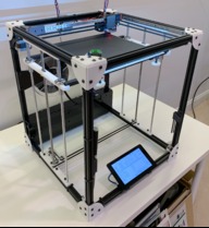
  1. SOA

    SOA Well-Known
    Builder

    Joined:
    Jan 22, 2020
    Messages:
    39
    Likes Received:
    53
    SOA published a new build:

    Read more about this build...
     
  2. fstkmaro

    fstkmaro New
    Builder

    Joined:
    Feb 9, 2020
    Messages:
    2
    Likes Received:
    0
    Nice looking build. I like all the detail put in. I have to look through the build but it seems that those are 10mm profiles, am I correct? If so, what the largest recommended size using those? I ask wondering about its firmness when printing at high speed. Thanks again and great job.
     
  3. SOA

    SOA Well-Known
    Builder

    Joined:
    Jan 22, 2020
    Messages:
    39
    Likes Received:
    53
    Thanks. The extrusions are 20mm x 20mm and it's quite rigid. I print between 100mm/s and 150mm/s. Attached is a close-up of a print.
     

    Attached Files:

  4. SOA

    SOA Well-Known
    Builder

    Joined:
    Jan 22, 2020
    Messages:
    39
    Likes Received:
    53
    This is my print farm. The top two are 450x450x350 and 450x450x550. The bottom two are both 450x450x450.
     

    Attached Files:

    taozeo and Semper Why like this.
  5. fstkmaro

    fstkmaro New
    Builder

    Joined:
    Feb 9, 2020
    Messages:
    2
    Likes Received:
    0
    Thanks for your quick reply. I really like this with no rails, just rollers. Interesting. I was just checking out the build with the 3z screws as well.
     
  6. xanderDK

    xanderDK New
    Builder

    Joined:
    Feb 10, 2020
    Messages:
    3
    Likes Received:
    0
    Cant say how much I love this build, you really worked through. I'm thinking about building one myself. But looking for a slightly bigger build area than 300x300 and now you posted this picture. The 450x450 ones you built are they build one the GridBot Two principles just with longer extrusions ?
     
  7. SOA

    SOA Well-Known
    Builder

    Joined:
    Jan 22, 2020
    Messages:
    39
    Likes Received:
    53
    Thanks. I was referring to the extrusion lengths used. 450x450x450 yields a build area of 300x300x350. It's easy to extend the Z lengths for taller builds. But making XY build areas larger means longer linear rails ($$$) and, most difficult, a larger heated bed.
     
  8. Uberjoe

    Uberjoe New
    Builder

    Joined:
    Jan 7, 2017
    Messages:
    1
    Likes Received:
    0
    Hi, I'm highly interested in building all this, but, quite don't understand wich firmware you took for driving the SKR.
     
  9. SOA

    SOA Well-Known
    Builder

    Joined:
    Jan 22, 2020
    Messages:
    39
    Likes Received:
    53
    I built Marlin 2.0.x from source so I could make modifications. The code is here: GridSpace/grid-bot
     
  10. drencken

    drencken New
    Builder

    Joined:
    Jan 20, 2019
    Messages:
    1
    Likes Received:
    0
    Hi @SOA - maybe I missed it but what material are the laser cut pieces?
     
    #10 drencken, Feb 16, 2020
    Last edited: Feb 16, 2020
  11. SOA

    SOA Well-Known
    Builder

    Joined:
    Jan 22, 2020
    Messages:
    39
    Likes Received:
    53
    it's all either 3mm or 6mm thick acrylic. of course, the pieces are printable. the 6mm pieces should be printed heavy / solid. the 3mm pieces are required to be strong. it should all be spelled out in the Onshape CAD model BOM.
     
  12. xanderDK

    xanderDK New
    Builder

    Joined:
    Feb 10, 2020
    Messages:
    3
    Likes Received:
    0
    One thing I can't find in the BOM is the type of camera/webcam suitable for the modeled mount? What fits? Thanks
     
  13. SOA

    SOA Well-Known
    Builder

    Joined:
    Jan 22, 2020
    Messages:
    39
    Likes Received:
    53
    I'm using the raspberry PI noir cam with a long ribbon cable.
     
    xanderDK likes this.
  14. xanderDK

    xanderDK New
    Builder

    Joined:
    Feb 10, 2020
    Messages:
    3
    Likes Received:
    0
    Okay thanks. Just finished printing the parts and next week its laser time. But the more I look into this the more questions :D

    What about endstops I can't find any on the model or BOM?

    How is the Pi connected to the SKR though usb or serial?
     
  15. SOA

    SOA Well-Known
    Builder

    Joined:
    Jan 22, 2020
    Messages:
    39
    Likes Received:
    53
    I'm using sensorless homing now. But endstops are easy to add, if you prefer. The SKR is connected to the PI with a USB cable.
     
  16. waynecto

    waynecto New
    Builder

    Joined:
    Apr 20, 2015
    Messages:
    2
    Likes Received:
    0
    i'd like to do a 600x600x600 version. my concerns it that is a lot of weight going up and down. can this design be modified so the extruder is going up and down instead?
     
  17. SOA

    SOA Well-Known
    Builder

    Joined:
    Jan 22, 2020
    Messages:
    39
    Likes Received:
    53
    CoreXY and H-Bot configurations are designed to take weight out of the print head to enable faster printing with fewer ringing artifacts. This is why they typically use bowden-style extruders. While it is possible to use CoreXY as a drive system for heavier loads, I would not recommend it. What you're looking to do is more like a CNC mill and should use either traditional rods to hold a cartesian driven head or a lead-screw drive system.

    My last thought on this is that the amount of movement in the Z is radically smaller and slower than all other motions. Unless you're printing metal or clay, I don't see these other trade-offs as worth it. Just scale up the GridBot plans and replace 20x20 with 40x40.
     
    Twest65 likes this.
  18. mrsapi

    mrsapi New
    Builder

    Joined:
    Apr 12, 2020
    Messages:
    2
    Likes Received:
    0
    hello, great job! Just one question, how did you implement the graphic interface in the 3d printer display? what do you have to do in order to make it work? thank you very much
     
  19. SOA

    SOA Well-Known
    Builder

    Joined:
    Jan 22, 2020
    Messages:
    39
    Likes Received:
    53
    The touch display is the standard 7" Raspberry Pi model. It's attached to a Pi running this GridSpace/grid-bot
     
  20. mrsapi

    mrsapi New
    Builder

    Joined:
    Apr 12, 2020
    Messages:
    2
    Likes Received:
    0
    you mean like a pi3 or 4, it's not really important which one. And I was wondering if the software interface would be easy to install, or it's something difficult, because at the first look it's not so clear for me. Or you can just import each part the folders contain?
     
  21. SOA

    SOA Well-Known
    Builder

    Joined:
    Jan 22, 2020
    Messages:
    39
    Likes Received:
    53
    I run some with pi3 and some with pi4. The software is designed to run with a single script command. After that you just configure wifi through the touch screen with a usb keyboard.
     
  22. Mark Rehorst

    Builder

    Joined:
    Aug 18, 2018
    Messages:
    9
    Likes Received:
    22
    It looks like a nice build, but I checked the CAD model and the belt segments that run from the corner pulleys to the ends of the X axis are not parallel to the Y axis guide rails. That's going to cause variable belt tension as a function of the extruder carriage position and distorted prints.

    More on proper belt layout here: Mark Rehorst's Tech Topics: CoreXY Mechanism Layout and Belt Tensioning
     
  23. SOA

    SOA Well-Known
    Builder

    Joined:
    Jan 22, 2020
    Messages:
    39
    Likes Received:
    53
    Mark, I understand your concern. And it's one I shared when I built the first prototype for this design a few years ago. However, several thousands of print hours later, I can report that is has had no material affect on the dimensional accuracy of prints. And I almost exclusively use my printers to print parts that require high dimensional accuracy.
     
  24. Joseph Hartley

    Builder

    Joined:
    May 9, 2020
    Messages:
    2
    Likes Received:
    0
    This looks like an amazing build and I'm just in the process of buying all of the required materials. However, I noticed that you didn't include the heater bed/surface in the BOM, what did you use?
     
  25. SOA

    SOA Well-Known
    Builder

    Joined:
    Jan 22, 2020
    Messages:
    39
    Likes Received:
    53
    I had the hardest time finding a reliable source of 24V heated beds and used several different ones in different build groups. Really, any 24V 310x310 heated bed will work. I've also used different surfaces. I started with 1 foot mirror tiles with a build-tak surface. And I also tried the Anycubic Ultrabase. Both worked well. Underneath the heated bed, I use a 1 foot square cork tile which helps the bed heat faster and retain heat better.
     
  26. Joseph Hartley

    Builder

    Joined:
    May 9, 2020
    Messages:
    2
    Likes Received:
    0
    okay, i guess it's just a matter of trial and error!
     
  27. Mandrak4

    Mandrak4 New
    Builder

    Joined:
    May 21, 2020
    Messages:
    7
    Likes Received:
    1
    Hi, noob here, sorry, This is my first 3D Printer DIY ever and i’m almost done with the mechanical part, but i felt some difficulty to understand some things, and i would be very happy if you can help me.

    1. In the CAD model i couldn’t see the extruder part, only the Nema 17 is appearing on the back side, and i do not know what to do.

    2. The software installation is in the raspberry pi or in the SKR 1.3?

    3. Can i use mouse and keyboard instead of touch Pi? Since i’m live in brazil, the touch pi is the only part that i was not able to find, and due to coronavírus i can not import.

    Sorry, i’m really noob, and sorry for my bad english, thank you for your attention!
     
  28. SOA

    SOA Well-Known
    Builder

    Joined:
    Jan 22, 2020
    Messages:
    39
    Likes Received:
    53
    1. you will need a bowden extruder driver like this https://www.amazon.com/gp/product/B07BMLD646
    2. the gridbot software installs on a PI, if you choose to use that instead of something like Octoprint. The Marlin firmware runs on the SKR.
    3. You can use a PC or laptop or Mac instead of a PI or just use a keyboard and mouse with the PI if you choose. You just need some way of sending the GCode to the Marlin firmware running on the SKR.
     
  29. Mandrak4

    Mandrak4 New
    Builder

    Joined:
    May 21, 2020
    Messages:
    7
    Likes Received:
    1
    Thank you!
     
  30. Mandrak4

    Mandrak4 New
    Builder

    Joined:
    May 21, 2020
    Messages:
    7
    Likes Received:
    1
    Hi, here i’m again, i just want to ask witch is the size used for the 3 mg12 rail and if i install the software that you made in the raspberry, I will be able to use with mouse and keyboard instead of touch
     

Share This Page

  1. This site uses cookies to help personalise content, tailor your experience and to keep you logged in if you register.
    By continuing to use this site, you are consenting to our use of cookies.
    Dismiss Notice