Welcome to Our Community

Some features disabled for guests. Register Today.

Double D-Bot 400mm x 400mm x 600mm

Discussion in '3D printers' started by Troy Proffitt, Nov 30, 2016.
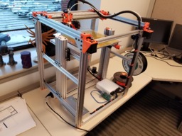
  1. CFerguson

    CFerguson New
    Builder

    Joined:
    Dec 6, 2018
    Messages:
    12
    Likes Received:
    1
    My cad skills aren't super, but I came up with my own measurements for a frame. I have a plan for my Z axis lead screws to mount them in the c-beam. But I'm not sure how well it will work. Ideally it won't have any play but it will be tricky to implement. Currently building my BOM, almost done.
     

    Attached Files:

  2. Troy Proffitt

    Troy Proffitt Well-Known
    Builder

    Joined:
    Oct 11, 2016
    Messages:
    126
    Likes Received:
    101
    Ok, sorry for the delay, here are the 2 3d printed pieces:
    Pulley Mount for D-bot z transmission by tmproff
    Cbeam Endmount by tmproff
    The Cbeam endmount just uses a standard 608 bearings (8mm ID)
    Yes, I'm using 20 tooth pulleys for the x/y
    for the leadscrews, I use these : https://www.amazon.com/gp/product/B017AR5QBS/ref=oh_aui_search_detailpage?ie=UTF8&psc=1
    here is the stepper and driver I used:
    https://www.amazon.com/gp/product/B019MFIOD8/ref=oh_aui_search_detailpage?ie=UTF8&psc=1
    https://www.amazon.com/gp/product/B016ZJS1FA/ref=oh_aui_search_detailpage?ie=UTF8&psc=1

    I'm not sure the belt length for the z, If I had to guess, it's around 1700mm
     
  3. CFerguson

    CFerguson New
    Builder

    Joined:
    Dec 6, 2018
    Messages:
    12
    Likes Received:
    1
    do you have any issues with the lead screws not staying down? do they walk up at all?
     
  4. Troy Proffitt

    Troy Proffitt Well-Known
    Builder

    Joined:
    Oct 11, 2016
    Messages:
    126
    Likes Received:
    101
    Nope, they dont move at all.
     
  5. CFerguson

    CFerguson New
    Builder

    Joined:
    Dec 6, 2018
    Messages:
    12
    Likes Received:
    1
    thanks a lot. do you have the files you remixed for your x y gantry?
     
  6. Troy Proffitt

    Troy Proffitt Well-Known
    Builder

    Joined:
    Oct 11, 2016
    Messages:
    126
    Likes Received:
    101
  7. CFerguson

    CFerguson New
    Builder

    Joined:
    Dec 6, 2018
    Messages:
    12
    Likes Received:
    1
    Thanks for the inspiration.

     
    Rick 2.0 likes this.
  8. Troy Proffitt

    Troy Proffitt Well-Known
    Builder

    Joined:
    Oct 11, 2016
    Messages:
    126
    Likes Received:
    101
    Wow! I love it. This is actually an improvement since the vertical attach midway up.

    Also, I switched to the top pieces that used aluminum plates. Adds a lot of rigidity:
    D-BOT - ALUMINUM CORNERS - MGN12H by ahntorage
     
    #38 Troy Proffitt, Jan 14, 2019
    Last edited: Jan 14, 2019
    CFerguson likes this.
  9. Aceso

    Aceso New
    Builder

    Joined:
    Jan 16, 2019
    Messages:
    1
    Likes Received:
    0
    Awesome build. i am looking at building me another core-xy printer. built two hypercubes now want to do a 400x400x600 D-Bot. I seen you used linear rails. what size? and how long?
     
  10. Troy Proffitt

    Troy Proffitt Well-Known
    Builder

    Joined:
    Oct 11, 2016
    Messages:
    126
    Likes Received:
    101
  11. CFerguson

    CFerguson New
    Builder

    Joined:
    Dec 6, 2018
    Messages:
    12
    Likes Received:
    1
    X y test video
     
  12. Troy Proffitt

    Troy Proffitt Well-Known
    Builder

    Joined:
    Oct 11, 2016
    Messages:
    126
    Likes Received:
    101
    Have you figured out where to put your z motor? Are you going to use gear reduction or bigger stepper like l did?
     
  13. CFerguson

    CFerguson New
    Builder

    Joined:
    Dec 6, 2018
    Messages:
    12
    Likes Received:
    1
    I have a nema 23. 20 tooth gears. 2mm pitch leads. I will be cloning your drive system, with some small modifications
     
  14. Troy Proffitt

    Troy Proffitt Well-Known
    Builder

    Joined:
    Oct 11, 2016
    Messages:
    126
    Likes Received:
    101
    Ok, I had an epiphany last night on a clean way to drive the z axis without using a Nema 23 / external driver and reduces the belt path quite a bit. I originally had my bed (which is quite large and heavy - 1/4 MIC 6 aluminum plate 15"x15") being driven by a single Nema 17 but using reduced gear ratio of 3:1. It had no problems moving the bed up and down. What do you think of this? You can slide the stepper mount along the 20x40 rail to add tension, no idler pulleys necessary. Also, no need for that long 20x80 piece between the 2 Cbeams cbeam_sample.jpg
     
    #44 Troy Proffitt, Jan 23, 2019
    Last edited: Jan 23, 2019
  15. fillefrans

    Builder

    Joined:
    Nov 11, 2018
    Messages:
    4
    Likes Received:
    0
    Hi Troy, if I understand the setup correctly you'd get less than 25% contact between the belt and pulley closest to the motor? I'm not sure what's recommended as minimum, but that seems less than ideal?
     
  16. Troy Proffitt

    Troy Proffitt Well-Known
    Builder

    Joined:
    Oct 11, 2016
    Messages:
    126
    Likes Received:
    101
    It would be quite easy to add an idler between those to pulleys to increase the contact, but it shouldn't be necessary. I'm going to be trying it out this weekend on a new D-bot build, and I'll take some pictures.
     
    fillefrans likes this.
  17. CFerguson

    CFerguson New
    Builder

    Joined:
    Dec 6, 2018
    Messages:
    12
    Likes Received:
    1
    I personally like the single z stepper idea. And having the beam across for me means it's more rigid. 20190123_234044.jpg
     
  18. Troy Proffitt

    Troy Proffitt Well-Known
    Builder

    Joined:
    Oct 11, 2016
    Messages:
    126
    Likes Received:
    101
    Just so you know, the new idea still uses a single stepper, but instead of a Nema 23 + external stepper, it will use a single Nema 17 that is driven off your main control board. The torque is there due to the gear ratio of 3:1. Overall, it's just a simpler design.
     
  19. CFerguson

    CFerguson New
    Builder

    Joined:
    Dec 6, 2018
    Messages:
    12
    Likes Received:
    1
    oh, I see what your saying. The picture doesn't quite represent your actually motor position in relation to the lead screws, I misinterpreted that. That looks like a good way to do it, and you can keep the motor external of an enclosure that way too, which would be nice.

    Yeah in my case i will be using a duet2 board, which is capable of driving a nema 23.
     
  20. Troy Proffitt

    Troy Proffitt Well-Known
    Builder

    Joined:
    Oct 11, 2016
    Messages:
    126
    Likes Received:
    101
    Ok, got it hooked up. Works very well!
    20190126_122040.jpg 20190126_122032.jpg
     
    CFerguson likes this.
  21. CFerguson

    CFerguson New
    Builder

    Joined:
    Dec 6, 2018
    Messages:
    12
    Likes Received:
    1
  22. Troy Proffitt

    Troy Proffitt Well-Known
    Builder

    Joined:
    Oct 11, 2016
    Messages:
    126
    Likes Received:
    101
    Progress this weekend:

    Matt_printer3.jpg
    Matt_printer1.jpg Matt_printer2.jpg
     
  23. CFerguson

    CFerguson New
    Builder

    Joined:
    Dec 6, 2018
    Messages:
    12
    Likes Received:
    1
    You went back to wheels on x-y?
     
  24. Troy Proffitt

    Troy Proffitt Well-Known
    Builder

    Joined:
    Oct 11, 2016
    Messages:
    126
    Likes Received:
    101
    This is a new printer im making for a co worker. He can upgrade rails / extruder in the future if he wants.
     
  25. Troy Proffitt

    Troy Proffitt Well-Known
    Builder

    Joined:
    Oct 11, 2016
    Messages:
    126
    Likes Received:
    101
    Controller came in the mail last night...got XYZ moving..still waiting for the MIC6 plate to come in the mail.

     
  26. Troy Proffitt

    Troy Proffitt Well-Known
    Builder

    Joined:
    Oct 11, 2016
    Messages:
    126
    Likes Received:
    101
    Printer is finally done. Delivery to new owner today!
    Printer_done.jpg
     
    Doug Wilson, patnap71 and GrayUK like this.
  27. GrayUK

    GrayUK Openbuilds Team Elder
    Staff Member Moderator Builder

    Joined:
    May 5, 2014
    Messages:
    1,668
    Likes Received:
    627
    Looks superb!! :thumbsup::thumbsup::thumbsup:
     
  28. Troy Proffitt

    Troy Proffitt Well-Known
    Builder

    Joined:
    Oct 11, 2016
    Messages:
    126
    Likes Received:
    101
    So I'm not happy with the solutions out there for D-bot carriages + linear rails + Titan Aero so I am designing my own. I'm going to cut the front / back out of aluminum (using my CNC machine), and tap all of the holes so no need for locknuts on the back. Here is what I have in mind. What do you think?
    carriage1.jpg carriage2.jpg carriage3.jpg carriage4.jpg carriage5.jpg
     
    #58 Troy Proffitt, Feb 12, 2019
    Last edited: Feb 12, 2019
    CFerguson likes this.
  29. patnap71

    patnap71 New
    Builder

    Joined:
    Apr 18, 2018
    Messages:
    12
    Likes Received:
    2
    Nice job. Do you have a BOM for the extrusion lengths and rails? Guessing 400x400x600? Thanks
     
  30. Troy Proffitt

    Troy Proffitt Well-Known
    Builder

    Joined:
    Oct 11, 2016
    Messages:
    126
    Likes Received:
    101
    I dont remember exactly the lengths of the 4 vertical pieces, but for the horizontal, I just used 500mm since they came from Openbuilds cut to that length for convenience (I did shave off a small portion to make sure all the horizontal pieces were exactly the same length). For the 4 vertical pieces, I started with 1000mm pieces and cut them down to about 750 I believe.
     
    patnap71 likes this.

Share This Page

  1. This site uses cookies to help personalise content, tailor your experience and to keep you logged in if you register.
    By continuing to use this site, you are consenting to our use of cookies.
    Dismiss Notice