Welcome to Our Community

Some features disabled for guests. Register Today.

Ultimo

Discussion in 'Other Builds' started by Brian Slee, Apr 27, 2014.
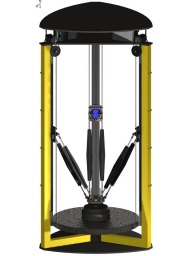
  1. Brian Slee

    Brian Slee Well-Known
    Builder

    Joined:
    Apr 26, 2014
    Messages:
    191
    Likes Received:
    59
    Hi Folks,
    Well it's been another busy week. We got all our parts back from the cutters, so this week we will be working on final assembly of the carriage plate and effector, in addition to getting the new post forms finished and filled with concrete. Guess I am going to have do another field day before I shoot the video of the pour...my poor shop is a disaster area....and Boo say's he needs more room for his QA work so "It's time for another field day" YAYYY!!! :p

    We are getting down to the wire...Only a little more than 4 weeks until the MakerFaire. This is really going to be a nail biter so

    Stay Tuned......
     

    Attached Files:

  2. John R

    John R New
    Builder

    Joined:
    Apr 28, 2014
    Messages:
    13
    Likes Received:
    2
    Looking great Brian!! Although Bo is right, need to organize a bit!
     
  3. Justin Edwards

    Builder

    Joined:
    Jul 19, 2014
    Messages:
    42
    Likes Received:
    10
  4. Brian Slee

    Brian Slee Well-Known
    Builder

    Joined:
    Apr 26, 2014
    Messages:
    191
    Likes Received:
    59
    Hey Justin,
    I am using the steel V-wheels in combination with the OpenRail for a linear guide. I did manage to get a hold of some of the anodized rail to go with them. The wheels and the rail are the lateral components and the rolling block assembly should carry most of the force in the perpendicular direction.

    Man you got a great start on your project....Hope you post up some pics as your build progresses :thumbsup:

    Right now we are tentatively located on the 3rd floor in the room next to the battle bots called the Founders Room. Most definitely stop by and say hi while you are there it will be great meeting you.
     
  5. Justin Edwards

    Builder

    Joined:
    Jul 19, 2014
    Messages:
    42
    Likes Received:
    10
    I went ahead and bought tickets. I've got the majority of my parts in now. Waiting on my belt, gears, and carbon rods. I'll probably get a piece of glass cut at ace and run without heat while I dial it all in. I tested out the 20x20 v-slot with a gantry plate while I wait on them to get the wider stock sent, it was even smoother than I imagined it would be.

    [​IMG]

    I didn't start a build on here yet, because I've been winging it with my 'design' I was thinking about bending some metal brackets (hydraulic press and drill press at work) or getting melamine laser cut and making some printed parts to attach it to the rail to keep everything squared up nicely.
     
  6. John R

    John R New
    Builder

    Joined:
    Apr 28, 2014
    Messages:
    13
    Likes Received:
    2
    Hi Justin - nice looking stuff! I especially am impressed with your spreadsheet - NICE!!!

    Sounds like you have access to some nice tools!

    Not sure how big of a Delta you're building, but if it's not too late, you live in the Orlando area and don't mind changing your plans a little you're welcome to use our forms! (attached jpg)

    Hope to see you at the Faire!
     

    Attached Files:

  7. Brian Slee

    Brian Slee Well-Known
    Builder

    Joined:
    Apr 26, 2014
    Messages:
    191
    Likes Received:
    59
    Hello All,
    Sorry for the long interval between posts but I have been devoting every second to getting Ultimo completed before the fair. I know I promised a video of the concrete pour, but my friend who does concrete got slammed with work and had to work the weekend. Unfortunately the schedule doesn't give us another week to wait for him to be available so we had to go ahead without the video. I will try and get a rain check from him for the next robot.

    I did manage to snap a few pics though, as I was prepping the new forms and the results so far. It turned out to be very easy all in all. I used a big drill with a mixing bit and did a half a bag at a time then just troweled it into the forms a scoop at a time. From starting to mix to filling all the forms took a little over half an hour. It worked out almost perfect, one bag did all three posts with a tiny bit left over.

    John got the brackets and the effector for final processing and already has the effector heading back my way so I can get the second pour done right away. Did I mention lately that YOU ROCK brother!!!!!!

    Add in a big field day and its been a very busy week...but we are getting close to putting it all together finally :thumbsup:

    We also decided to add an LCD controller and use an off the shelf hot end for the prototype since our development schedule is short.

    Oh and boo got his new executive office

    The first batch of concrete is going to be cooking in the forms for another day, but I will get more pics when they come out. This next week should see some big developments as the second pour happens and the linear rails get mounted, So

    Stay Tuned.......
     

    Attached Files:

  8. Brian Slee

    Brian Slee Well-Known
    Builder

    Joined:
    Apr 26, 2014
    Messages:
    191
    Likes Received:
    59

    Awesome to hear that we will get to meet you at the fair. Yep the v-slot is great, I did a little testing on mine when I got the parts in and it was smooth as butter :)

    If you are wanting a device to square up two pieces of v-slot I don't recommend using laser cut melamine for the job. The edges where the laser cut the forms I got were not straight due to the width of the melamine and the focal characteristics for the laser. at about 85 to 90 pct of the cutting depth the beam begins to deform. If you have the tools go with the bracket IMHO or look at having something cut on the water jets instead. The aluminum parts that were cut out of 1/2" plate came out beautiful.
     
    #128 Brian Slee, Aug 19, 2014
    Last edited: Aug 19, 2014
  9. Brian Slee

    Brian Slee Well-Known
    Builder

    Joined:
    Apr 26, 2014
    Messages:
    191
    Likes Received:
    59
    Hello There Kids and Kiddetes,

    Well It's been another busy week. The posts are all done and the effector is back in town after John rocked it out. I put my calipers on that puppy and the brackets are within a 1/10 of a mm. First moves are getting tantalizingly close.

    Stay Tuned......
     

    Attached Files:

    Mark Carew likes this.
  10. Tweakie

    Tweakie OpenBuilds Team
    Moderator

    Joined:
    Jan 18, 2014
    Messages:
    784
    Likes Received:
    326
    Looking good Brian :thumbsup:

    Tweakie.
     
  11. Mark Carew

    Mark Carew OpenBuilds Team
    Staff Member Moderator Builder Resident Builder

    Joined:
    Jun 28, 2013
    Messages:
    2,745
    Likes Received:
    2,410
    WOW! that is looking good :thumbsup:
    Keep up the good work
    Mark
     
  12. John R

    John R New
    Builder

    Joined:
    Apr 28, 2014
    Messages:
    13
    Likes Received:
    2
    OM goodness - that thing's a monster! Take care & keep up the great work!!
     
  13. Rob Taylor

    Rob Taylor Master
    Builder

    Joined:
    Dec 15, 2013
    Messages:
    1,470
    Likes Received:
    746
    Ok, thoughts:

    1) Big thumbs up for WWII-style concrete machinery. :thumbsup: That idea is in my future too, at some point, most likely on a metal lathe though I may try it on the mill that I have planned next (which itself is to help build a laser cutter next year!). I'd like to find a more environmentally-friendly alternative at some point too, but it works for the time being.

    2) Are there prepackaged delta-bot control systems, or are you going to have to come up with a novel method of control? I see a whole lot of simultaneous trigonometry involved over the more simple Cartesian systems, given that it'll still have to run from Cartesian vector->step commands. It seems like an X-Y gantry would still have saved the space over an X-Y table, but allowed a far more simplified control system and ease of reproduction/maintenance. It's a bit late to be thinking about this now, obviously, but unless there are solid software/firmware solutions already in place, the next stage will be quite difficult. But I assume you've done your research as far as that goes.

    3) Plasma cutter. Win. Can't wait to see that.

    4) Are you planning on having the head self-selectable? I saw you were trying to fit the print head to the bottom of what looked like a spindle enclosure, so I'm guessing you're going somewhere in that direction. A GUI to select between functions isn't much use if the machine itself can't automate its own function selection, after all! I'm envisaging some kind of 5-axis type mill bit selector, with heads that sit in place near the top until needed, with power cables individually going out each third of the support structure. Some kind of mechanism brings them into the centre, drops them into the main head holder and locks them in place. If you have to switch out heads and print platforms and clamps and stuff between runs anyway, it seems like separate control circuits that you manually plug and unplug would be no less convenient.

    Those are my initial thoughts, anyway. You may have already covered them and I missed it, though I did read all 5 pages! It's looking very impressive.

    What was the fiber-reinforced concrete that you used? I don't think I saw a label for that; I foresee a Home Depot trip in my near future...
     
  14. Brian Slee

    Brian Slee Well-Known
    Builder

    Joined:
    Apr 26, 2014
    Messages:
    191
    Likes Received:
    59
    Hi Rob,
    Thanks for taking the time to read my ramblings and for the compliments.

    To get started I picked up a batch of files from RWG Research web site because it was all in a nice zipped folder. Here is the link
    http://open-source-energy.org/rwg42985/russ/RWGresearch Delta Softwere files 9-25-13.zip

    This is the same set of source files used on the Rostock, so I should be able to us it with some minor changes to the configuration files for the size differences. And yes it does involve a bit of trig to get the coordinates for X,Y, and Z. I think most of the Deltas are using reverse kinematics these days since it cuts down on the calculations the controller has to perform. I have wondered if it might be easier and faster to just go with an array for all valid points and move from point to point using simpler math.

    Initially it will be all manual changes and tool selection for the different options. But the Arduino has plenty of room for expansion and we are not going to be pushing it hard since we are getting our step resolution by using change pulleys vs microstepping the controller, so it would be relatively easy to assign some of the digital I/O pins to a sensor arrangement to auto ID the tool later on.

    BTW I switched out from the fiberglass reinforcement when I went with the new forms and added rebar instead since I had much more volume to work with over the round forms. The fiberglass reinforced cement mix is available at any of the local home improvement stores.
    http://www.homedepot.com/p/Quikrete-50-lb-Surface-Bonding-Cement-123050/100318462
     
  15. Rob Taylor

    Rob Taylor Master
    Builder

    Joined:
    Dec 15, 2013
    Messages:
    1,470
    Likes Received:
    746
    No worries, it's an interesting experiment with hopefully very practical results. And it looks awesome, more like an industrial robot than most OpenBuilds projects.

    Well that's handy! That should be almost all of the way there, just needs a little adapting to milling- which I just had a thought about right now. The actual depth of a cut will be increasingly limited as you move towards the outside of the platform, due to the arms interfering with the workpiece, unless your milling head has its own separate Z actuator. The form factor is fine for printing and cutting, but I think you might hit some unfortunate limitations on milling. Looking at the image below, you'd have to perform some kind of check prior to hitting start, like integrate the arms' total under-volume over the entire toolpath and see if the model "pokes out of" that volume when they're superimposed in 3D space.

    I don't think you need to waste memory storing arrays, because the vector calculations for inverse kinematics on this are relatively simple- there are only two possible positions of each belt for any given point in space of the head, and only one that's higher in z (positive theta) than the head itself, so each arm can be calculated independently. If you assign the centres of the three hinges connected to the belts exact 2D coordinates from the bed, you're only solving for Z. For the other end of the arm, I'd probably use a constant to adjust from the centre of the head to the centres of the arm pivots for calculation purposes. If you're keeping it all positive for the 2D coords (ie. arbitrary "top left" of the bed is 0,0- or an assigned column hinge nearby) which is probably advisable with Arduino's limitations on variables, the calculations should be really quite straightforward:

    (i,j,k)+(i',j',k') = (x,y,z)

    |(a,b) - (x,y)| = d

    θ = cos^-1(d/l)

    h = l sinθ

    z+h=c

    where (i,j,k) is tool center location, the primed version is the constant transform between the tool centre and the pivot, (x,y,z) is head pivot location and (a,b,c) is column gantry pivot location. d is flat distance from pivot to pivot, or from the side of the head to the side of the gantry- the bottom of the right angle triangle. l is length of the arm, and h is the height from where d ends to the gantry pivot- the riser of the right angle triangle.

    deltatrigdiagram.jpg

    ...Which seems a lot when it's for all three arms on every step, but I don't think it's an issue for even Arduino-level computing power. I'm assuming that the Arduino files you have do all of that though, right? There's still the issue with milling, though, particularly at the extremities.

    Nice, once you have that, a whole custom GUI to go with it will be perfect. Maybe an entire self-contained package that reads STLs and AIs and stuff too. But I'm getting ahead of myself.

    Awesome. Fiber bonding and rebar both, I think, for me. Rebar should protect the overall integrity as the fibers protect the local integrity. It would also reduce the size of the rebar that I'd need and bond more tightly to the rebar with the glass fibres wrapping around it.
     
  16. Brian Slee

    Brian Slee Well-Known
    Builder

    Joined:
    Apr 26, 2014
    Messages:
    191
    Likes Received:
    59
    Hi All,
    Here are the latest pictures. Just over a week to go until the MakerFaire...It's gonna be close :nailbite:

    Stay Tuned......
     

    Attached Files:

  17. Brian Slee

    Brian Slee Well-Known
    Builder

    Joined:
    Apr 26, 2014
    Messages:
    191
    Likes Received:
    59

    Hi Rob,
    We are definitely aiming towards getting industrial type capabilities while keeping the overall footprint as small as possible and we are also committed to keeping the costs down to a level where almost anyone can afford to have one in the garage.

    I don't think there will be a problem with depth at the edges. Remember that the X and Y are achieved by varying the effector arms in relation to each other and the Z axis is set by moving all three carriages simultaneously in the same direction. My rail extends a little bit below my work table so even with one of the arms fully extended it should be capable of reaching -Z numbers (unless the concrete is in the way ;O).

    I am not sure which exact formulae are used in the set of files I have. I haven't gotten around to looking at the source code yet. But it does do all of the calcs necessary for parallel robot operations in 3DOF. My thought on the arrays is based on the fact that memory is dirt cheap and that current Arduino architecture doesn't use even a thousandth of the available memory on the SD cards that are being used with LCD controller. My understanding is that the Arduino can produce a max step frequency of 16Khz for the Delta due to the processing load induced by the calculations required per step. I thought that if an array was used in conjunction with the embedded operators it might greatly increase the step rates.

    lol Great minds think alike...I was also thinking some of it might be easily done by adding a batch file or autorun setup on an SD card that could even reflash the firmware for different tool options.

    I went with the Maximizer mix because of the weight to volume. Using it saved me several hundred pounds. I did not add any fiberglass for this one but I think for the next one I will add it in to the mix. Now that I have the forms it will be really cheap to experiment with different mixes to get the best results...I think I have about $30 or so total into the concrete, rebar and threaded rod.
     
    #137 Brian Slee, Sep 5, 2014
    Last edited: Sep 5, 2014
  18. Brian Slee

    Brian Slee Well-Known
    Builder

    Joined:
    Apr 26, 2014
    Messages:
    191
    Likes Received:
    59
    Thanks Tweakie :)
     
  19. Brian Slee

    Brian Slee Well-Known
    Builder

    Joined:
    Apr 26, 2014
    Messages:
    191
    Likes Received:
    59
    Thanks Mark for all of the encouragement and support
     
  20. Brian Slee

    Brian Slee Well-Known
    Builder

    Joined:
    Apr 26, 2014
    Messages:
    191
    Likes Received:
    59
    Definitely a little too big for the desktop ;)
     
  21. Rob Taylor

    Rob Taylor Master
    Builder

    Joined:
    Dec 15, 2013
    Messages:
    1,470
    Likes Received:
    746
    That sounds similar to my general goals too! Yay! :D

    That's what I'm saying- because the arms aren't fixed like a gantry, but vary in their height depending on the head position, there could be problems with depth on certain models that appear to be compatible with the geometry of the cutter but actually aren't once it starts moving around:

    ultimocrash.jpg

    It works ok as long as deep cuts are only made in the centre. Of course, the size of the spindle+mount+Z-rail is also something other people have to bear in mind on their Cartesian projects, so I'm not sure it's so much a limitation as a difference. Just something I thought of, anyway, I don't think it'll be relevant in day-to-day operations.

    I'm not sure that you'll see a significant difference in speed between calculations and memory access operations, though it's probably worth experimenting with given that the trigonometry might be relatively heavy for it (I don't know, for example, how many terms it calculates the Taylor series to for the sin operator). Reflashing directly from a control PC (or miniPC) might be the best idea given Arduino's sketch size limitations.

    Interesting. I just thought earlier that I may want the unit to be carryable from desk to workbench or something, so I may have to consider a different concrete density. I don't want a 1.5kW spindle hitting 6061 Alu to make it vibrate around all over the place either, though. I may even do some kind of layering of steel meshes and tubing and different types of cement. It needs to be simple and easily reproducible by non-experts, but sturdy.
     
  22. Justin Edwards

    Builder

    Joined:
    Jul 19, 2014
    Messages:
    42
    Likes Received:
    10
    Brian, I'm almost done with my delta now too. I have a Machinekit (linuxcnc) setup that's been tested with deltas and has much better accel / jerk handling than the arduino based boards. [​IMG]

    Have you seen the 4th axis delta? That might be a good fit for your scenario. I actually fried two Beaglebone blacks with what I think was a bad PSU, if I can get that solved I wouldn't mind letting you test it out with your setup. I'm running Drv8825s on that board which can only run at 2amps but they can go up in voltage.
     
  23. Brian Slee

    Brian Slee Well-Known
    Builder

    Joined:
    Apr 26, 2014
    Messages:
    191
    Likes Received:
    59
    Hi All,
    Well it's a mad scramble this week to get finished by showtime. I don't have much time for posting and replying this week but here is a pic of the latest progress. Wish me luck we have until Friday to get it done.
     

    Attached Files:

  24. Tweakie

    Tweakie OpenBuilds Team
    Moderator

    Joined:
    Jan 18, 2014
    Messages:
    784
    Likes Received:
    326
    Good luck Brian :thumbsup: - perhaps get Boo doing a bit of overtime and take care of you back (and toes) when lifting the completed frame into the truck.

    Tweakie.
     
  25. Rob Taylor

    Rob Taylor Master
    Builder

    Joined:
    Dec 15, 2013
    Messages:
    1,470
    Likes Received:
    746
    ^Ha! It really is a transporter chamber.

    Looking good! Looking forward to discussing it post-Faire. :thumbsup:
     
  26. Brian Slee

    Brian Slee Well-Known
    Builder

    Joined:
    Apr 26, 2014
    Messages:
    191
    Likes Received:
    59
    Hi All,
    Well after a week of no sleep, I am happy to report that we made our deadline and got Ultimo all together and ready for the fair.......

    Unfortunately one of my biggest worries was realized and the frame did not survive the ride.

    Sighhhhhhhh....

    Oh well. The good news is that replacing the concrete frame is a relatively inexpensive fix. The bad news is that it can't be redone fast enough to demo the operation.
     

    Attached Files:

  27. GrayUK

    GrayUK Openbuilds Team Elder
    Staff Member Moderator Builder

    Joined:
    May 5, 2014
    Messages:
    1,668
    Likes Received:
    627
    Wow! Really sorry mate! after all that. :(:(

    May be a dumb question, but why does it have to be in concrete?
    Is there no alternative? :confused:

    Better luck with Mk 2 :thumbsup:

    Gray
     
  28. Brian Slee

    Brian Slee Well-Known
    Builder

    Joined:
    Apr 26, 2014
    Messages:
    191
    Likes Received:
    59
    Thanks Gray...But I am undeterred and this won't scuttle my ship.

    There are lots of alternatives to concrete. All of them much more expensive for similar capabilities. Keep in mind that Ultimo wasn't designed for portability. Concrete does a lot of stuff well but traveling isn't one of them since it only take one good bounce to exceed the deflection capabilities of the mix. So for now Ultimo MK2 will still be concrete, maybe a little beefier for MK2
     
  29. Justin Edwards

    Builder

    Joined:
    Jul 19, 2014
    Messages:
    42
    Likes Received:
    10
    You can put in an acrylic additive to help with that. You could probably fix what you have by wrapping a mold around, taping it up, it and pouring in some resin. We'll be heading that way in a bit.
     
  30. Rob Taylor

    Rob Taylor Master
    Builder

    Joined:
    Dec 15, 2013
    Messages:
    1,470
    Likes Received:
    746
    From the research I've been doing recently, for the type of size and capability you want this machine to have, you're gonna need support beams 2-3x as thick, made from polymer/mineral concrete, with carbon fibre or similar (not steel, apparently- some coefficient of expansion thing) tensile reinforcement. This is something I'm currently actively researching and hopefully doing some experimentation with as well. Industrial-capability machines, though, tend to weigh several hundred kg even at our sizes.

    Also, Portland cement doesn't stop moving whilst curing for around 2 years, as the water not used in the hydration process slowly leaves the structure. The larger the object, the more it shrinks- so your upright beams are/will be shrinking in the Z axis significantly. Bolting together your rails whilst the beams are still curing means that the anchor points are being held in place as the concrete shrinks around them, putting the concrete under significant tensile stress. Since it's designed to compress (millions of PSI) rather than stretch (a couple thousand PSI?), this will inevitably cause significant stress weakness in the structure and inability to transport.

    Also, the steel reinforcement is very effective at transmission of vibration- so even if it had worked, it may not have survived a particularly fast or tricky metal milling job.

    I wish I could have contributed this a few weeks ago when you could have reacted in time, but I've literally just learned it in any kind of detail over the last couple of days. :( I still have a long way to go, too.

    Acrylic additive is a good call though, if you can knock together a melamine jig to hold it in time, though the curing may not be done until after the weekend at this point.
     

Share This Page

  1. This site uses cookies to help personalise content, tailor your experience and to keep you logged in if you register.
    By continuing to use this site, you are consenting to our use of cookies.
    Dismiss Notice