Welcome to Our Community

Some features disabled for guests. Register Today.

Vulcan Maxtrudr

Discussion in '3D printers' started by Keith Davis, Jan 12, 2018.
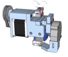
  1. Keith Davis

    Keith Davis Veteran
    Builder

    Joined:
    Dec 11, 2013
    Messages:
    506
    Likes Received:
    393
    Keith Davis published a new build:

    Read more about this build...
     
  2. crystaldragon141

    Builder

    Joined:
    Oct 27, 2016
    Messages:
    8
    Likes Received:
    10
    In fairness E3D recommends a 40mm 0.9 deg motor now. The motor is ~48 oz which is 144 oz. (Of course this is using the holding torque for these motors which has little to do with dynamic torque)
     
  3. Keith Davis

    Keith Davis Veteran
    Builder

    Joined:
    Dec 11, 2013
    Messages:
    506
    Likes Received:
    393
    YES they do. The pancake looks good in all of their promotional pictures, but in the small print it turns out they wouldn't use a puny pancake motor on their own printer. But with the 40mm motor that extruder has the same weight and performance of a 5 year old Wade/Greg getup. Yes it looks better than that old printed gear getup, but that $100 price tag is strictly for looks. One would be better off using a 35mm motor on a Titan Aero as it is lighter than a 40mm and still gives plenty of power to push even 3mm filament through a 1.0 volcano nozzle at high speed. But only the 35mm motor from Robotdiigg, which is 200gm while all other 35s are 230gm.
     
  4. JustinTime

    JustinTime Veteran
    Builder

    Joined:
    Dec 18, 2013
    Messages:
    756
    Likes Received:
    252
    Keith, I looked at the parts and for the life of me I can't figure out how the nut for the tension spring, for the lever arm, is held in place in order to be able to adjust the tension. I was expecting the screw to go through the part and the nut to be outside, but it's not.
     
  5. Keith Davis

    Keith Davis Veteran
    Builder

    Joined:
    Dec 11, 2013
    Messages:
    506
    Likes Received:
    393
    The slot that the spring and screw fit into is the width of the nut, that prevents the nut from turning.
     
  6. JustinTime

    JustinTime Veteran
    Builder

    Joined:
    Dec 18, 2013
    Messages:
    756
    Likes Received:
    252
    I got that, that it prevents it from turning. My question is what prevents it from going up and down so that the pressure can be applied? The way I see it now the nut will slide up if you turn the wing nut.
     
  7. Keith Davis

    Keith Davis Veteran
    Builder

    Joined:
    Dec 11, 2013
    Messages:
    506
    Likes Received:
    393
    As you tighten the wing screw the nut does move up, compressing the spring. Since the wing screw remains stationary against the bottom of the slot, that compression increases tension against the lever arm.
     
  8. JustinTime

    JustinTime Veteran
    Builder

    Joined:
    Dec 18, 2013
    Messages:
    756
    Likes Received:
    252
    OK, now I got it! :)
     
  9. Andrew Burgess

    Builder

    Joined:
    Jan 27, 2018
    Messages:
    20
    Likes Received:
    1
    do you have a drawing package I can look at and use to create the parts in Solidworks? something in PDF format?
     
  10. Keith Davis

    Keith Davis Veteran
    Builder

    Joined:
    Dec 11, 2013
    Messages:
    506
    Likes Received:
    393
    Andrew
    I'm reworking the extruder at this point. I plan to publish a rework next week. You should be able to import the STL files into Solidworks, right?
     
  11. Andrew Burgess

    Builder

    Joined:
    Jan 27, 2018
    Messages:
    20
    Likes Received:
    1
    Well with the student version of 2017/2018 it tends to complain about missing properties and wont let me make drawings.. I also think my instructor wants me to enter all that information from a set of PDF drawings. *sigh* shoot me now.
     
  12. Keith Davis

    Keith Davis Veteran
    Builder

    Joined:
    Dec 11, 2013
    Messages:
    506
    Likes Received:
    393
    I could save each part as a png, then with ms paint you could 'print' them to a pdf.
     
  13. Andrew Burgess

    Builder

    Joined:
    Jan 27, 2018
    Messages:
    20
    Likes Received:
    1
    Anything that works. =-)
    I was starting to get desperate.
     
  14. Keith Davis

    Keith Davis Veteran
    Builder

    Joined:
    Dec 11, 2013
    Messages:
    506
    Likes Received:
    393
    Printing the rework now. Should be proofed out next week.

    I take it you are working on a class project, sort of a 'how does it work, why does it work' assignment. If that's the case, and I fall behind on the rework, what if I just end up doing pngs of all the original parts?
     
  15. JustinTime

    JustinTime Veteran
    Builder

    Joined:
    Dec 18, 2013
    Messages:
    756
    Likes Received:
    252
    I hope it will use the same non 3d printed parts as the original one! It takes forever for parts to come from China and the parts for the original one are still swimming across the ocean! :nailbite:

    I got the closed loop belt but the big pulley is not here yet which is why I didn't already print the parts. ;)
     
  16. Keith Davis

    Keith Davis Veteran
    Builder

    Joined:
    Dec 11, 2013
    Messages:
    506
    Likes Received:
    393
    Yes, only change is to 3d printed parts. Problem was that the idler bearing eventually gets cocked to an angle pushing the filament unevenly on the drive gear groove. The only hardware change is the drive shaft across the top is now 5mm longer than it needs to be, no big deal it can stick out that much.
     
  17. Andrew Burgess

    Builder

    Joined:
    Jan 27, 2018
    Messages:
    20
    Likes Received:
    1
    That's brilliant! Yes, the final project is basically proof that we know how to translate a set of drawings into 3D parts and then take those parts and assemble them. I wanted to do a full 3D printer but I've noticed a prevalence of people using programs OTHER than SolidWorks to do their designs. I've spent way too much time trying to translate/import/exchange the parts into compatible drawings. Starting to thing the industry standard isn't SolidWorks at all. Ah well, I'm getting a good sampling of experience with a bazillion other CAD programs. What did you say you used to design the vilcan? did you put together a BOM as well?
     
  18. Keith Davis

    Keith Davis Veteran
    Builder

    Joined:
    Dec 11, 2013
    Messages:
    506
    Likes Received:
    393
    Here's a plan for you:
    Download and install

    Sketchup Make Download SketchUp

    It is a free program (I used it to design the Vulcan). Although Sketchup Make is free, it is supported by a billion dollar company. Their Sketchup Pro is an industry standard for the home building industry. Make is supported by a large community through Sketchucation and Youtube channels. Their Sketchup Warehouse contains more than a million parts submitted by their user base which can be imported directly into a project. Because of all that Sketchup is rapidly becoming the standard for this kind of CAD design work.

    Then, download http://3dwrx.com/vulcan/assembed.skp

    Open the assembled.skp in Sketchup Make.
    That is the fully assembled Vulcan Maxtruder current version. It is fully assembled so you can see how it all fits together. All printed parts and hardware parts are there. You can copy any part, open a second instance of Sketchup and paste that part in that instance, then use Sketchup's File>Export>2D Image to create a PNG of the part. You can rotate parts any way you want for that image, or even use multiple parts for an image that shows them in an exploded relationship view. Using MS Paint you can then "Print" the PNG as a PDF.

    Also, consult Assembly Vulcan Maxtrudr Index for a detailed tutorial on assembling a current version Vulcan. Feel free to use any of the images or explanations in your assignment that can fit your purpose.
     
  19. Andrew Burgess

    Builder

    Joined:
    Jan 27, 2018
    Messages:
    20
    Likes Received:
    1
    assembed.skp is a dead link unfortunately. Everything else is got.
     
  20. Keith Davis

    Keith Davis Veteran
    Builder

    Joined:
    Dec 11, 2013
    Messages:
    506
    Likes Received:
    393
  21. JustinTime

    JustinTime Veteran
    Builder

    Joined:
    Dec 18, 2013
    Messages:
    756
    Likes Received:
    252
    Any news on the newest version yet? Got the bearings yesterday. Big pulley still swimming across the ocean.

    I need maybe two bearings but had to buy 20!!! And...paid only $2 shipped!!!
     
  22. Keith Davis

    Keith Davis Veteran
    Builder

    Joined:
    Dec 11, 2013
    Messages:
    506
    Likes Received:
    393
    NEW VERSION

    [​IMG] [​IMG]
    [​IMG] [​IMG]
    [​IMG]

    This version is much easier to assemble. The idler lever holds the bearing in the center of the two-part lever, ensuring that the bearing remains square with the drive gear. The rear body is mounted directly to the rear of the motor instead of being mounted to the top cross-span, giving the entire extruder greater stability. There are 3 semi-circles that are inserts to hold 2 M5 & 1 M3 nut into recesses in the main body for assembly.

    A fully assembled Sketchup file (with screws etc) is at
    http://3dwrx.com/vulcan/master.skp
    A STL file with the above parts is at
    http://3dwrx.com/vulcan/unassembled.stl

    The BOM:

    4- m3x10mm button head screws
    3- m3x25mm socket head screws
    3- m3 nuts
    3- m5 nuts
    2- m3x35mm socket head screws
    2- m5x25mm srews
    1- 5mm dia fender washer
    1- m5x40mm wing screw
    1- m5x15 screw
    1- m5x85 shaft (threaded rod)
    [​IMG]

    [​IMG] [​IMG]
    [​IMG] [​IMG]
    [​IMG]
     
    JustinTime likes this.
  23. Andrew Burgess

    Builder

    Joined:
    Jan 27, 2018
    Messages:
    20
    Likes Received:
    1
    Rocking!
    I had to resort to a set of drawings of a sterling engine. got the drawings of 4 assemblies and 24 parts last Friday and had them completed by Sunday evening. LOL Now I just have to produce an eBOM and a new set of drawings done by me and I can ace the final project. =-)
     
    Keith Davis likes this.
  24. Keith Davis

    Keith Davis Veteran
    Builder

    Joined:
    Dec 11, 2013
    Messages:
    506
    Likes Received:
    393
    Sounds awesome!!
    Please post that project in the Projects section here. I just may be interested. That sounds like a great project for a high school tech class. It would kill a few birds with one build.
     
  25. JustinTime

    JustinTime Veteran
    Builder

    Joined:
    Dec 18, 2013
    Messages:
    756
    Likes Received:
    252
    Keith, what are the 3 C-clips/bushings for? I couldn't find them in the .skp.
     
  26. Keith Davis

    Keith Davis Veteran
    Builder

    Joined:
    Dec 11, 2013
    Messages:
    506
    Likes Received:
    393
    They are in http://3dwrx.com/vulcan/master.skp They are white, not red.

    When M5 & M3 nuts are pushed into the backside recesses of the main body piece, these bushings are pushed in to hold those nuts in place during assembly. They are sized to remain in the recesses.
     
    JustinTime likes this.

Share This Page

  1. This site uses cookies to help personalise content, tailor your experience and to keep you logged in if you register.
    By continuing to use this site, you are consenting to our use of cookies.
    Dismiss Notice