Welcome to Our Community

Some features disabled for guests. Register Today.

7050 Sphinx

Discussion in 'CNC Mills/Routers' started by Michael.M, Jul 15, 2017.
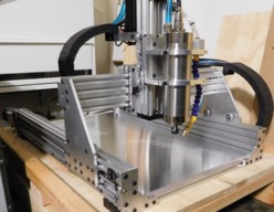
  1. Sprags

    Sprags Well-Known
    Builder

    Joined:
    Nov 23, 2017
    Messages:
    154
    Likes Received:
    13
    Is the rule of thumb for the Sphinx machine that the standard OpenBuild lead screws are 40 to 50mm longer than the c-beam length of the axis it's installed on? Such that if the X-axis c-beam is 503mm the lead screw should be about 543mm in length?
     
  2. Michael.M

    Michael.M Veteran
    Staff Member Builder Resident Builder

    Joined:
    Jan 21, 2017
    Messages:
    432
    Likes Received:
    264
    I suggest you download SketchUp (free edition) and also the complete Sphinx machine model .skp file and then you can dissect the individual parts. I forget how long the original screws were because I swapped mine out for heavier duty 3/8" ACME screws. Mine now extend beyond the end plates as you can see in my pictures. This allows me to tension them from the outside. I think the original specs are included in Kyo's build guide though.
     
  3. Sprags

    Sprags Well-Known
    Builder

    Joined:
    Nov 23, 2017
    Messages:
    154
    Likes Received:
    13
    Thanks...I did get hand wheels that I can use to manually adjust the gantry positions...and in reality I see that if the screws extend out longer they don't affect anything functionally. I have been looking at a build that was created in solidworks. I should have thought about verifying the length in the model.

    So far my only gripe is a few of the wheel assemblies do not spin freely and a few others have a gritty feel while spinning the wheels. And yes I made sure I installed the spacer inbetween the bearings.
     
  4. Michael.M

    Michael.M Veteran
    Staff Member Builder Resident Builder

    Joined:
    Jan 21, 2017
    Messages:
    432
    Likes Received:
    264
    Try taking the bearing out of the wheels and flipping it around.
     
  5. Sprags

    Sprags Well-Known
    Builder

    Joined:
    Nov 23, 2017
    Messages:
    154
    Likes Received:
    13
    OK...what's the secret to getting the bearing out so I can flip it around?
     
  6. Michael.M

    Michael.M Veteran
    Staff Member Builder Resident Builder

    Joined:
    Jan 21, 2017
    Messages:
    432
    Likes Received:
    264
    No secret there. I'd personally find a small shaft or bar (sub 5mm), pass it through the inner race of one bearing and press on the inner race of the opposite bearing. It's not like they're pressed in a metal bore. You're probably just going to have to get creative but at least you only have do do a couple of them! I'm sure you'll figure it out. ;)
     
  7. Michael.M

    Michael.M Veteran
    Staff Member Builder Resident Builder

    Joined:
    Jan 21, 2017
    Messages:
    432
    Likes Received:
    264
    I have an extra small wheel with bearings installed and it's definitely a tight fit but the shim inside moves back so you can get something up against the race.
     
  8. Michael.M

    Michael.M Veteran
    Staff Member Builder Resident Builder

    Joined:
    Jan 21, 2017
    Messages:
    432
    Likes Received:
    264
    If you use something sharp, be careful not to stab your hand on the other side
     
  9. Michael.M

    Michael.M Veteran
    Staff Member Builder Resident Builder

    Joined:
    Jan 21, 2017
    Messages:
    432
    Likes Received:
    264
    One of those automotive "hook" type picks would probably pull one of the bearings out. Seriously though, I had a couple of the small wheels do the same thing and I think I just flipped the wheel around or something. As long as the wheel spins true, I don't think it's critical. You can also try loosening the nyloc nut slightly.
     
  10. TurfnSurf

    TurfnSurf New
    Builder

    Joined:
    Jan 6, 2018
    Messages:
    32
    Likes Received:
    17
    Can I get some clarity on what level of accuracy you have gotten with this machine? thanks!
     
  11. CNCMD

    CNCMD Journeyman
    Builder

    Joined:
    Jul 29, 2017
    Messages:
    148
    Likes Received:
    114
    Not to speak about someone else's machine, but I can tell you about mine which is a Sphinx design as well.

    I can achieve accuracy of greater than 0.05mm consistently.

    Here are what I feel are the keys to this:
    1) Step tuning - Tuning the steps/mm to ensure accuracy. I find the best way to do this is to cut 2x2 blocks, and measure and adjust accordingly.
    2) Backlash (Nuts) - Need to ensure that backlash has been eliminated. I run dual anti-backlash nuts.
    3) Backlash (Collars) - I determined another source of backlash was the collars on the lead screws. Unless you ensure a flat spot for the set screw, the collar will sit slightly cocked, and not fully engaging the end bearing, and therefore introducing backlash into the system. I corrected this with clamping lock collars.
     
    #312 CNCMD, Feb 21, 2018
    Last edited: Feb 21, 2018
    GrayUK and Michael.M like this.
  12. TurfnSurf

    TurfnSurf New
    Builder

    Joined:
    Jan 6, 2018
    Messages:
    32
    Likes Received:
    17
    dual anti-backlash nut

    I get 3 - makes sense, but can you detail out 2 for me a bit more?
     
  13. CNCMD

    CNCMD Journeyman
    Builder

    Joined:
    Jul 29, 2017
    Messages:
    148
    Likes Received:
    114
    There is some adjustment to the anti backlash nuts. Therefore you need to adjust them properly based on feel/tension.
     
  14. Sprags

    Sprags Well-Known
    Builder

    Joined:
    Nov 23, 2017
    Messages:
    154
    Likes Received:
    13
    Because of the wheel and bearing materials I thought that an attempt at disassembly of the wheels would damage either the wheel or bearings however I actually was able to get one of the larger ones disassembled. Sure enough upon closer inspection I found that the outer race on both bearings was recessed on one side and flush on the other so installing the bearings with the recessed outer races and consequently protruding inner races towards the center of the wheel. That was the shim between the two bearings contacts only the inner races.

    It seems to me that I don't remember hearing or reading anything relating to this in the build guide or the YouTube build videos. Perhaps OpenBuilds should include at least a note pertaining to the orientation of the bearings in the assembly process.
     
  15. JeromeL

    JeromeL New
    Builder

    Joined:
    Oct 25, 2015
    Messages:
    13
    Likes Received:
    0
    Hi @Michael.M

    Nice build! I would like to build the same machine as you and I have a quick question for you ?

    What is the length of the Cbeam you used for the Z axis for your build ?

    Thanks !
     
  16. Michael.M

    Michael.M Veteran
    Staff Member Builder Resident Builder

    Joined:
    Jan 21, 2017
    Messages:
    432
    Likes Received:
    264
    I think it's either 280 or 300mm. I'll verify this when i get home.
     
  17. Michael.M

    Michael.M Veteran
    Staff Member Builder Resident Builder

    Joined:
    Jan 21, 2017
    Messages:
    432
    Likes Received:
    264
    It might even be 270. You basically just need enough space to completely move your spindle out of the way. Any longer than that is unnecessary.
     
  18. Sprags

    Sprags Well-Known
    Builder

    Joined:
    Nov 23, 2017
    Messages:
    154
    Likes Received:
    13
    I think I made mine 280mm. Yep...when I got home I measured 280mm.
     
    #319 Sprags, Feb 27, 2018
    Last edited: Mar 3, 2018
  19. Sprags

    Sprags Well-Known
    Builder

    Joined:
    Nov 23, 2017
    Messages:
    154
    Likes Received:
    13
    Even though I made sure all the beams for the frame and the axis were cut exactly to the dimensions I planned for the X axis distance between plates is greater than it theoretically should be. My X axis is planned to be 600mm so I cut the c-beam to 603mm. I guess some tweaking is required.
     
  20. Michael.M

    Michael.M Veteran
    Staff Member Builder Resident Builder

    Joined:
    Jan 21, 2017
    Messages:
    432
    Likes Received:
    264
    My Z axis cbeam is 270mm
     
  21. Michael.M

    Michael.M Veteran
    Staff Member Builder Resident Builder

    Joined:
    Jan 21, 2017
    Messages:
    432
    Likes Received:
    264

    Your x axis should be 3mm over your desired length to account for gantry plate clearance.
     
  22. JeromeL

    JeromeL New
    Builder

    Joined:
    Oct 25, 2015
    Messages:
    13
    Likes Received:
    0
    Thanks for the information !
     
  23. NeeqOne

    NeeqOne Well-Known
    Builder

    Joined:
    Mar 3, 2018
    Messages:
    46
    Likes Received:
    27
    Michael, which shielded cable did you use for the spindle? Thanks.
     
  24. DA98520

    DA98520 New
    Builder

    Joined:
    Sep 27, 2015
    Messages:
    11
    Likes Received:
    0
    Did you find a way to incorporate linear rails yet with custom plates?
     
  25. Michael.M

    Michael.M Veteran
    Staff Member Builder Resident Builder

    Joined:
    Jan 21, 2017
    Messages:
    432
    Likes Received:
    264
    I used a 4 conductor 16ga shielded cable from McMaster Carr. I can't find the receipt at the moment.
     
  26. Michael.M

    Michael.M Veteran
    Staff Member Builder Resident Builder

    Joined:
    Jan 21, 2017
    Messages:
    432
    Likes Received:
    264
    This is still a WIP. Are you looking to build a Sphinx type machine with linear rails?
     
  27. DA98520

    DA98520 New
    Builder

    Joined:
    Sep 27, 2015
    Messages:
    11
    Likes Received:
    0
    Yes i am, i have most parts laying around from other builds so wanted a good way to use it.
     
  28. Michael.M

    Michael.M Veteran
    Staff Member Builder Resident Builder

    Joined:
    Jan 21, 2017
    Messages:
    432
    Likes Received:
    264
    Well I have the majority of the changes worked out. I took a break from this project to work on my mini mill i recently purchased. I'm now starting to work my way back lol. It's crazy how I can get totally sidetracked sometimes but I really wanted a small manual mill for making changes to parts without having to setup the CNC. Anyway, I have the Z axis done. I started a new build called "Sphinx Evolution". If you click on my profile, you should find it. Now that I know someone else is interested I'll try to stay focused!
     
  29. mortorojo

    mortorojo New
    Builder

    Joined:
    May 4, 2016
    Messages:
    6
    Likes Received:
    1
    Can you give us a copy of your template for modifying the x-axis stand off plate?
     

Share This Page

  1. This site uses cookies to help personalise content, tailor your experience and to keep you logged in if you register.
    By continuing to use this site, you are consenting to our use of cookies.
    Dismiss Notice