Welcome to Our Community

Some features disabled for guests. Register Today.

C-beam Router rack and pinion

Discussion in 'CNC Mills/Routers' started by rpagewood, Sep 24, 2015.
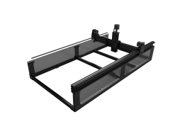
  1. rpagewood

    rpagewood New
    Builder

    Joined:
    Jun 29, 2015
    Messages:
    3
    Likes Received:
    8
    rpagewood published a new build:

    Read more about this build...
     
    #1 rpagewood, Sep 24, 2015
    Last edited: Sep 24, 2015
    Tom Allen likes this.
  2. Mark Carew

    Mark Carew OpenBuilds Team
    Staff Member Moderator Builder Resident Builder

    Joined:
    Jun 28, 2013
    Messages:
    2,745
    Likes Received:
    2,410
  3. Rlwilson2

    Rlwilson2 New
    Builder

    Joined:
    Feb 3, 2015
    Messages:
    9
    Likes Received:
    0
    I like the concept. I am building a CNC Router Parts 48x48 right now.. I would suggest using gear reduction on your drives... CNCRP uses 3-1. Gives you better resolution and allows motors to spin in better torque range. Also remember to make bumpers to limit travel from going off track...
     
  4. Tom Allen

    Tom Allen New
    Builder

    Joined:
    Aug 4, 2015
    Messages:
    12
    Likes Received:
    3
    rpagewood,
    I like your design, especially the rack/pinion. Seeing the design in Fusion 360 is also great. I'm trying to learn Fusion, but it is a steep learning curve for me. I wounder if there is an easier CAD program to use on the hobby level.
    I look forward to following your project.
    Tom
     
  5. Tom Allen

    Tom Allen New
    Builder

    Joined:
    Aug 4, 2015
    Messages:
    12
    Likes Received:
    3
    rpagewood,
    I see you are using rack/pinion presumably for precision, yet you have it driven by belts. Care to comment on this pairing? Why not go gear-direct? Is it true that rack/pinion is the most accurate?
    P.S.: Obviously, you can tell I'm very much an amateur.
    Tom
     
  6. Florian Bauereisen

    Florian Bauereisen Well-Known
    Builder

    Joined:
    Feb 24, 2014
    Messages:
    188
    Likes Received:
    60
    Hi,
    In Pic one it seems to be missing a ballrace. Like this it will jam.
    I would consider to gear down (like 1:2) too in order to get a better balance between resolution and speed.
    Right now you have a fast machine but might be short of power.

    Maybe my abandoned U.E. project (to be found here) might give you some ideas.

    Just food for thought

    greets

    flo
     
  7. Tracy Ranson

    Tracy Ranson Well-Known
    Builder

    Joined:
    Nov 4, 2014
    Messages:
    88
    Likes Received:
    32
    I really like the rack and pinion set up. You may want to add some sort of adjustable spring loaded belt tension device, perhaps go with a more aggressive belt...something that won't slip under a load. I would also go with a ratio of 3:1. I have used XL belts in a similar set up and never had an issue. Check out this link on R&P You will see that they too use a belt drive setup. http://www.cncrouterparts.com/standard-rack-and-pinion-drive-nema-23-p-50.html
     
  8. rpagewood

    rpagewood New
    Builder

    Joined:
    Jun 29, 2015
    Messages:
    3
    Likes Received:
    8
    Hi All,

    Thanks for the feedback. I was originally inspired by the machine from cncrouterparts.com. I think the belt drive to R&P is probably a necessity for the reduction. I'll add a larger lower pulley on the timing belt and change the Y axis around a bit to have the same setup.
    I'll put up some more pictures as I progress.

    Cheers
    Russell
     
  9. Serge E.

    Serge E. Journeyman
    Builder

    Joined:
    May 6, 2014
    Messages:
    730
    Likes Received:
    251
    I really like the design. A nice way to get those Y steppers back on the inside of the foot print instead of hanging out ...

    Just need to make certain there is no possible slippage from the belt driven rack & pinion. What kind of belt and pinions are you thinking of using ?
     
  10. Karl Miller

    Builder

    Joined:
    Apr 14, 2014
    Messages:
    25
    Likes Received:
    4
    Would like to hear more about the use of gear reduction with the rack and pinion. I don't exactly understand how to do that correctly. I want a simple design, and it doesn't require the stepper on the inside, so maybe that will help.
    I am working on a 4x5 ox using the c-beam and a rack/pinion drive for the x&y axis also because I need more stability and ability to cut PCBsPCB s, so stiff granularity is paramount, but speed is not critical, as long as the aluminum cuts can be made without "welding".
    Any suggestions on a source low-profile rack and gear set?
     
  11. Jonny Norris

    Jonny Norris Well-Known
    Builder

    Joined:
    Aug 17, 2014
    Messages:
    495
    Likes Received:
    95
    Without a planatary gearbox on a light weight setup I'd recommend a 4mm wide rack is probably the most you'd want to go to get the required preload on it otherwise you will find it will jerk Badly.

    With the belt drive might be worth considering a nylon rack and pinion which will mesh better with less preload.

    For example On my 15mm steel rack I'm running around 50kg of preload and this is only because I'm maxed out, I'm told 150-200kg is optimal! I do feel I would benefit with some more so now making subtle modification to get it up a bit. But if I simply mesh the pinion no preload, it runs like it has Parkinson's.

    Obviously bigger rack and more weight so an extreme example but important you allow for adjustable preload. One way is if you are bolting the rack to the profile with tnuts, you will find a small amount of play with the bolts in loosly, worth testing before designing the plates I.e if you push the rack as far as it will go away from where the pinion will be and place the pinion at full mesh in that position in the design. Pushing the rack down and tightening bolts will give you your preload.

    Also you may want to double up the bearings on the belt to pinion drive with a block, tapered bearings and nuts to compress the bearings similar to that of a the fixed ballscrew support. This will stiffen the drive up to allow for the preload and help prevent any positional errors.
     
    #11 Jonny Norris, Oct 9, 2015
    Last edited: Oct 9, 2015
  12. Karl Miller

    Builder

    Joined:
    Apr 14, 2014
    Messages:
    25
    Likes Received:
    4
    Thank you @Jonny Norris for the advice.
    Just to clarify, the machine I am building is going to be 4' x 4' made of the c-beams and the rack inside the C. I say this because you seemed to suggest that I was looking at building a lightweight machine, which is the opposite of my intention.

    I feel a little too ignorant for asking, but :
    1. How are you measuring preload?
    2. What do you mean by "better mesh"? Is this just a tighter fit between rack and pinion gear?
    3. Why does a narrower rack provide better preload?
    4. You mention using nylon to get better mesh? Why? Wouldn't that get sloppier over time?
    5. Which bearings and block are you referring to when suggesting doubling them up on the belt to rack mechanism? I am not picturing that. Maybe if had a link to an example you wouldn't mind sharing?

    Thanks for all the thoughtful suggestions.
    Karl Miller
     
  13. Jonny Norris

    Jonny Norris Well-Known
    Builder

    Joined:
    Aug 17, 2014
    Messages:
    495
    Likes Received:
    95
    No problem,

    I personally measure preload with a torq wrench, its important you have adjustment on the mesh.. my motors pivot offset of center of pinion and on opposite offset i have two blocks that can rotate. one on the gantry plate and one on motor plate, I then have a bolt that going through both blocks that have lock nuts either side of one of the blocks.. This allows me to adjust and measure the preload ie the force applied to tightening the nut.

    yes mesh is tighter fit.

    A narrower rack does not provide better preload, it requires less. Nylon will mesh better without preload than a steel rack would without preload. 3nm motors such as a nema 23, doesn't sound that powerful but i have two shifting 250kg at 5m/min and its easy to forget if with a cutting load, the pinion is trying to push away from the rack. We are not talking masses of preload required for the design your talking about as it is light in weight in respect to the weight the motors can move and therefore less resistance. but say you have a 3nm motor driving it.. then ideally you would have 3nm of force acting to stop the pinion trying to push away. Equal and opposite forces.

    3nm is 30.6 kg-cm, so a 5mm rack requires 1.5nm and thats the theory anyway.

    Nylon might well be a bad example, there are definitely some better plastic racks out there. something ive only heard of being used for cnc not really looked into it. The theory behind why they would require less preload is a bit beyond me im afraid but something to do with hardness.

    In the design i see you have a pulley on a shaft that goes through the gantry plate to the racks pinion.. I cant see much in the way of a bearing block to support the shaft? All i was suggesting it needs there is a block of alumium say 30mm thick with a large diameter hole through it.. you then fit one compression bearing on the shaft and insert into the block so the bearing is snug in the hole and flush with one side, you then put two spacers on the shaft and another compression bearing that finishes flush with other side of block. You then have a thread on the shaft eitherside of block you fit nuts on and tighten. Like the fixed side of a ball screw support. Or possibly just use one like this:


    [​IMG]

    You would need a shaft machined and you would most likely either need to either extend the motor shaft or move the motor to facilitate that extra length, but you could mount this on a swinging plate as i have with my motors to give you adjustable preload. but you will most certainly need to make space for a better supported pinion shaft, too much play using a single bearing, and you also going to need some tension on the belt so you have two mechanisms working against each other at the moment. Probably want to flip the rack the other way up so the forces of the belt and preload are opposing.
     
  14. Jonny Norris

    Jonny Norris Well-Known
    Builder

    Joined:
    Aug 17, 2014
    Messages:
    495
    Likes Received:
    95
    Your x looks good btw.. just the dual y's that need a bit of attention. Slot the x motor mounting holes will allow you to get some preload there.

    Also are you going to add a sprung idler wheel for the belt? or sliding motor for belt tension?

    sorry if i have sounded at all condescending, people say i often do, if so its not intentional just how i work through things i guess. And this is of interest at its been something im considering with my ox. Still working through the kinks on my full diy build, which ive very much learnt the hard way with certain things. so far i've replaced the motor mounts and modified gantry plates due to this preload issue.. a £400 ballscrew because i chose to listen to just one guys advice, Need to overhaul the z and its frame is going to be changed in a big way also, will likely take years before i will be completely happy with it. Well worth the effort though.
     
    #14 Jonny Norris, Oct 15, 2015
    Last edited: Oct 15, 2015
  15. The Todd

    The Todd New
    Builder

    Joined:
    Aug 19, 2014
    Messages:
    11
    Likes Received:
    3
    :thumbsup: Like the pinion setup... I'll be following :thumbsup:
     
    Tom Allen likes this.
  16. Mad Machinist

    Builder

    Joined:
    Dec 29, 2015
    Messages:
    1
    Likes Received:
    1
    I'd be happy to help you. I am learning Fusion 360 and so far I am doing ok. Still have a ways to go though.

    I have 20+ years as a machinist if it helps.
     
    Tom Allen likes this.

Share This Page

  1. This site uses cookies to help personalise content, tailor your experience and to keep you logged in if you register.
    By continuing to use this site, you are consenting to our use of cookies.
    Dismiss Notice