
There is some useful information here, but readers should be aware that Ooznest's workbee design has moved on since this report was written and there has been significant developments in the software.
Alex
Other people have logged their Workbee builds, so this will not be a blow-by-blow account of how I built my Workbee. Mine has the new Duet controller, so I will pass on a few comments about installing that, plus a few problems I encountered with the mechanical build.
I bought my Workbee as a complete kit from Ooznest - it came beautifully packed, but with only the mechanical assembly manual - the rest are available online with a couple of videos for setting up the Duet.
Ooznest have a well deserved reputation for writing very clear manuals and the mechanical assembly went fairly smoothly - just a few points to watch out for.
You could build this with the tools recommended (Allen keys, 8mm spanner and crosshead screwdriver), but the build will go a lot quicker if you also have Allen head screwdriver bits, a flexible screwdriver extension and an 8mm nut spinner or socket.
The instructions don't always cover every detail - when assembling the X carriage you are sensibly advised to attach the Z limit switch and thread the wire from it through the hole opposite. The plate this hole is in is handed - there is only one hole on one side for the Z limit switch wire and neither the text or the pictures make this clear.(Yes I did have to take it apart and re-build it).
Check every T nut - I had to re-thread 23 of mine! I had no problems with any of the drop-in T nuts, but the others were really very poor.
When you assemble the drag chains one of the screws to fix the moving end of the Y drag chain has to go between the 20x40 and the C-beam. The nut is captive in the drag chain mount, so the only way I found to do that one up was to use an Allen screwdriver bit in a flexible driver.
The rest of the assembly went without any major hitches until I came to wire up and configure the Duet.
When threading cables through the drag chain it is a good idea to thread them all through in one go. If you try to thread the limit switch cables through with the stepper motor cable already in place it will get in the way. Thread something fairly stiff - I used a length of heavy electric wire - about twice the length of the drag chain and used insulating tape to attach each of the cables needed to it - attach them seperately so that the connectors are not all in the same place and the insulating tape covers anything that might catch as it goes through the drag chain.
I am not impressed with the quality of the connectors - one of the crimp contacts for one of the Y steppers was broken - half of it was still attached to the wire but came out of the plastic receptacle when I plugged it in leaving the springy bit that contacts the header on the Duet inside. You do get 100 replacements with the duet, so at least I didn't have to wait for a replacement cable or re-thread it through the drag chain.
To set up your Duet you must watch Ryan Locke's videos on Ooznest's U-Tube channel in conjunction with the online manuals. I really struggled with manuals for setting up my (ethernet version - the wi-fi version is better served) until I watched Ryan's videos when it all became clear. You will need to pause and rewind often though -Ryan whizzes through the process at some speed.
So, my workbee was assembled, the Duet configured and the workbee firmware installed - time to see if it all worked. All three axes jogged as they should, the Z and X axes homed perfectly, but the Y axis failed. The illustration showing where to mount the Y axis limit switch is wrong - the text is correct (the picture shows the limit switch at the very end of the Y axis C-beam - it needs to go a bit away from the end - the text says 13mm, mine works fine at about 10mm) and flip the microswitch - the illustration shows the end of the lever pointing to the centre of the machine - it needs to point to the outside..
Having fixed that I jogged the machine around a bit more and, horrors! opposite sides of the Y axis started to move in opposite directions. Back to those connectors on the ends of the stepper motor cables - they are not supposed to spark are they? One of the stepper motor cables had not gone on to the header on the Duet properly and one wire was only making intermittent contact. The headers on the Duet are really flimsy - they have a plastic lug which is supposed to latch onto the connector on the cable. At least one of these had failed completely because it is really thin, flimsy plastic. There are better connectors out there guys - this is not an area to save a few pence.
This all sounds really negative so far, and some bits are, but overall I am really pleased with the Workbee and am looking forward to using it now that it is all working. Now I just need to get my head around Fusion 360 - and Ooznest have written a post processor for the Duet controlled Workbee that should at least make the CAM side of Fusion 360 straightforward.
One point I forgot to mention was regarding the X axis limit switch wire - I couldn't get it to stay in the slot in the 20x40 until I remembered I had some clips for attaching things to greenhouse framework.
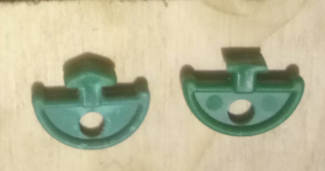
I trimmed them slightly to get a better fit. Sorry about the very blurred image - it was cold in my cellar where I have my workshop.
In case anyone was wondering about the power of this machine and the nema 23's, I did something really stupid and left a g cramp holding a workpiece to the spoiler board sticking up. The machine ripped the spoiler board apart when it collided with the g cramp. No other damage fortunately.
IMPORTANT
By default the duet settings are set to allow moves without homing. This MUST be unticked - it disables soft limits which means that you can drive your machine into the framework. Also, if you set up your limit switches as the manual recommends you will have to reduce your Y axis to 760mm in config.g, not 770 as Oozenest say.
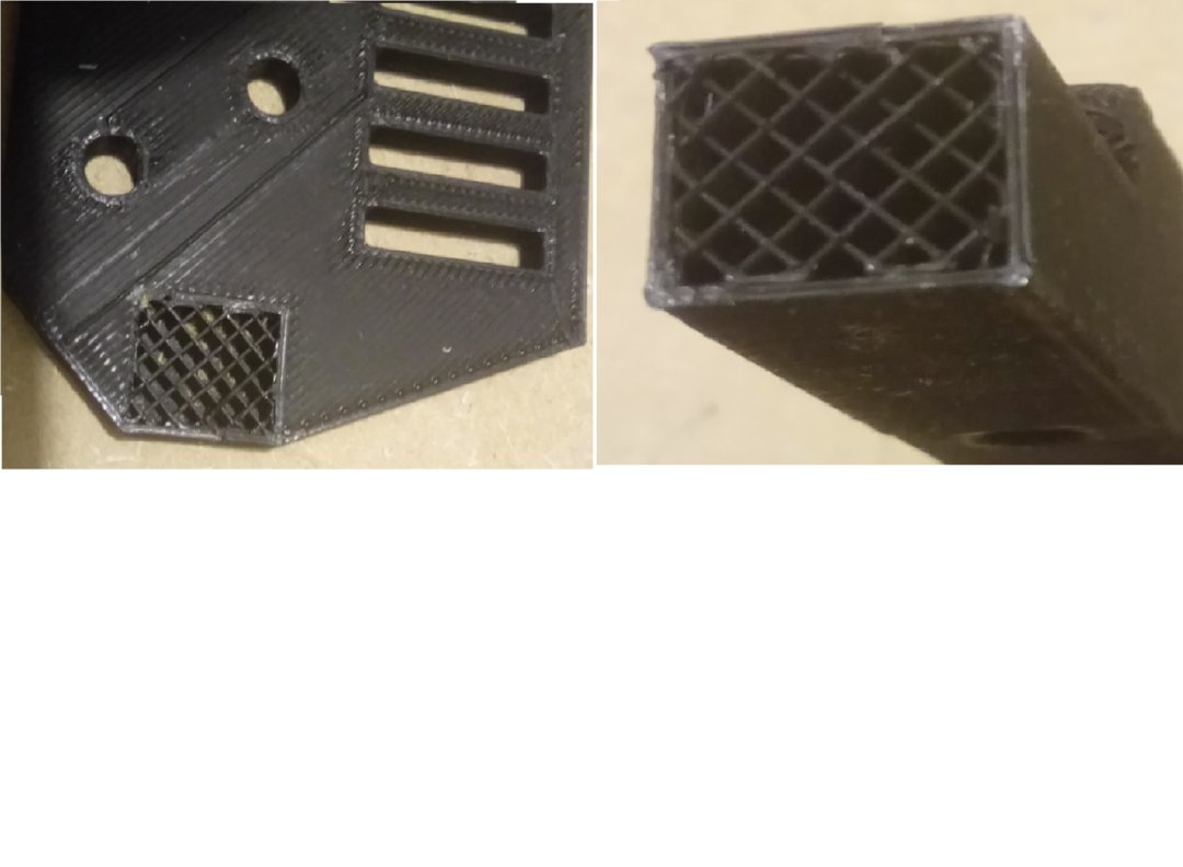
I accidentally caught the fixed end of my Y drag chain with my sleeve and snapped the mounting bracket. I was really pleased with the response from Oozenest, who sent a replacement part within 24 hours.
This morning I was modifying my machine to give a greater depth of cut, so I decided to fit the replacement mounting bracket. 3D printing lays the plastic down in layers, so the junction between two layers will always be a weak point, but there are ways of weakening it even further ... (see pics)
The modification I was doing involved changes to the bed supports. I obtained 4 metre lengths of 20/20 T slot and some corner brackets, removed the existing 20/80 bed supports and the 20/40's from the end frames and attached the 20/20's to the end frames. It seems quite rigid as it is, but I might need to add some more support under the 20/20's.
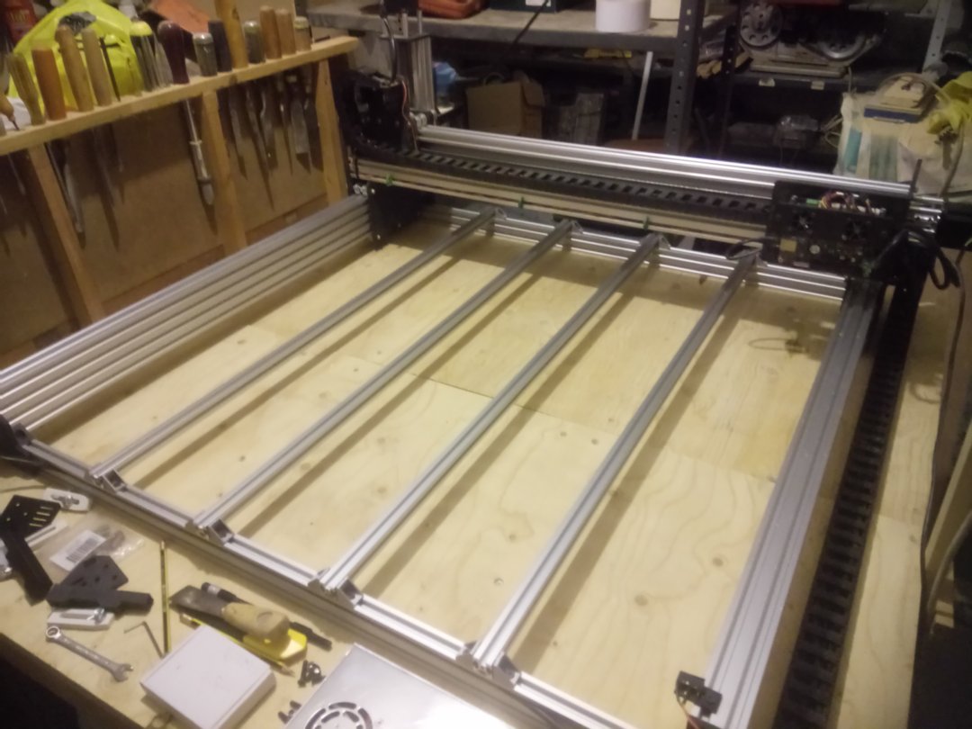
As well as being able to lower the Z axis further for thicker materials, I should now be able to mount my spoiler board by loosely fitting screws to T nuts and sliding it on. (I have been using "drop-in" T nuts into the top slot on the bed supports but, as they are under the spoil board, it's a real pain getting them all to line up)
I also now have 3 lengths of 20/80 and 2 lengths of 20/40 V slot going spare - I guess I'll have to think of something else to build!
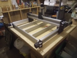
Workbee with Duet controller
Build in 'CNC ROUTER BUILDS' published by Alex Chambers, Jul 31, 2020.
Workbee 1010 with Duet controller from Ooznest
-
-
Build Author Alex Chambers, Find all builds by Alex Chambers
-
- Loading...
-
Build Details
- Build License:
-
- CC - Attribution - CC BY