


Hi Guys-n-Gals,
I've ordered a WorkBee screw driven full kit from Ooznest which should be arriving early/mid March. I ordered a 1.5 Kw Chinese spindle and VFD combo from a company in Germany - they arrived today along with a spindle mount. Minor bend to the electrics end cap on the spindle.
Next job is to check the run-out on the spindle to make sure its not worse than it looks...
I've built a solid bench for the WorkBee, acting as both it's assembly area and its working position.
Photos of the spindle:
The VFD is a Huanyang Model: HY01D523B 1.5Kw rated at 7.0A. The spindle is 1.5Kw with a ER16 collet running 0-24000 rpm. Wired both up this morning and all seem OK. Very quiet even when ramped up to full rpm compared to my routers. Need to check the run-out but taking the motor up and down through its range there was no vibration.
Added an earth connection from the motor casing to pin 4. Numbering on my plug is set out differently to others that I've seen posted. Looking directly at the connector on the top of the spindle, with the register pin at the 12 O'clock position my numbers run anti-clockwise: top left is pin 1 round to top right which is pin 4.
My WorkBee should (I hope) arrive next week. Postie delivered some small end mills today - I think it will be a little while before I trust myself to these...
Great day 9th March - My WorkBee arrived this morning. Extremely well packed in two main boxes. A long box containing the extrusions and long threaded rods, second box containing everything else...
The second box contained smaller boxes each clearly labeled with its own content.
Photos attached show the content of sub boxes, all labeled. I need to sit down now and check everything and start making wheels...
Wheels made, and assembled the left and right Y axis plates so far today. I have one wheel on a non adjustable axle that touches and rotates when one of the other wheels is rotated and moves the C beam. But if I rotate it it doesn't have enough traction to move the beam on its own. I'll tinker with that later. Quite pleased with day 1 so far.
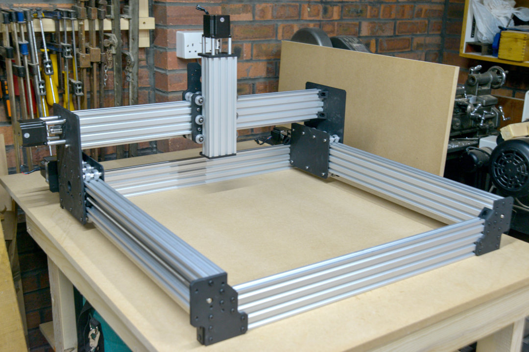
Frame virtually completed. Need to make a decision on the spoil board height, insert it's supports and the spoil board itself. A few more photos of the frame.
Frustrating time (for me) yesterday after getting the simplicity of frame together I came to assembling the power supply. I found the shortness of the cables extremely awkward another cm in length would have made it so much easier especially as I'm having to work with one and a bit hands. But got there in the end.
I taped cables to a long steel rule to feed them through the drag chains so that was fine.
Confused myself at one point thinking the limit switches should be located to null the machine in the front left position - had a coffee and realised that they were for the machines 'home' position back right, not the working home position front left.
So today will be assembling the remaining electrics, securing cables and with luck a test run without a router just to make sure things are working.
Plugged it in and turned on the power and lots of lights - just like Christmas...
Take the computer to the workshop later and have a better test.
Well I ran into a couple of glitches but with a few emails to Ryan at Oosnest it now works. Just been cutting air at the moment but I has now run a few small files generated in Inkscape as tests.
Time to finish the router mounting and try cutting some materials.
I've uploaded an image of a logo trial All letter pockets have been cut to a 2mm depth with a 0.6mm cutter to clear the bulk, the capital M has had a single pass with a 0.4mm cutter. I had set the feed and plunge speeds too low so I stopped the program at that point. I'm going to revisit the tool paths too and clean them up with a bezier curve rather than the snap to I used for these cuts. The snap to picked up noise from the jpg file at the letter edges and that noise was transferred to the cuts as light juddering. Probably better to redo the jpg and save at 1200 dpi rather than the 150 dpi I used. That will reduce the noise at the back/white interface. The toolpath was generated in Cut2D and saved directly as g-code.
Been working with the WorkBee after doing some calibrations on the X & Y axlii. Getting the hang of Vectric Cut2D desktop now and started delving into fusion 360's trial. Added an image of a pyramid guitar bridge I'm wanting to make in Bog Oak but will cut one in softwood first to try things out. The underside has a 20 foot radius inscribed so will be interested to see how that comes out.

I've purchased a 1.5kW water cooled spindle as the Makita was just too loud - what a difference, not just in noise levels but stability as well - using a small aquarium pump but I think a little larger version is probably safer. Current one is stated at 1100 lpm but I think something double that volume would be better. After running at 12k rpm for 40 min I couldn't feel any heat in the spindle casing.
Well I've been using the WorkBee for a while now, the addition of the water cooled spindle has been a real bonus. It's heavier than the Makita 0700C router but the WorkBee copes easily. My only problem came when one of the thrust collars slipped allowing the X axis to wander slightly - a wider collar and a second grub screw would be better - perhaps even a couple of flats so the collar can be engaged better with the bearing before tightening...
Apart from that its been superb. I'm beginning to get the hang of Fussion360 and Cut2D. I wanted originally to using freeware but Fusion I'm using as an enthusiast so not had to pay for that. I did purchase Cut2D and its been a pleasure to use the gcode works unedited with UGS, Fusion (for me) needs some initial code editing out to run with UGS and that I found by drawing a simple square in fusion and Cut2D and comparing the opening gcode - removing 4 or 5 lines from the fusion listing.
Just been working on a guitar fretboard which is coded partly with Fusion 360 (16 inch crown radius), and part Cut2D Fret slots, inlay pocket, and inlays. Images above
WorkBee 750x750 build
Build in 'CNC ROUTER BUILDS' published by fwm891, Apr 19, 2018.
This CNC build is to help with some areas of my guitar builds - mainly inlays but some body work as well where appropriate. I expect it will be used for lots of other things once I get to know what it's capable of (sorry - what I'm capable of!).
-
-
Build Author fwm891, Find all builds by fwm891
-
- Loading...
-
Build Details
- Build License:
-
- CC - Creative Commons Public Domain (CCO 1+)
Reason for this Build
Built the WorkBee because it gave me the precision I felt I needed for my inlay work and was man enough to handle the heavier cuts in hardwoods for other guitar parts. I started looking at a different forum and the advice from there (which was good) was taking me to a precision I didn't need and work handling beyond requirements. Plus Oosnest answered all my enquiries without being pushy - thanks Guys.Inspired by
the OX cnc builds. Wanted to add a screw drive rather than the belt drive and found the WorKBee already had them... -
Parts list
Qty Part Name Part Link Comments 1 WorkBee screw driven 750x750 kit from Oosnest Link Superb kit -
Attached Files:
-


