EDIT 28/07/18 : Changed the machine state from build in progress to complete!!This is great and sad news.. Great because I have fully operatinonal machine and it is cutting much better than I expected. Sad because I have really enjoyed building it and digging into CO2 laser. There few more things which can be done - red laser crosshair to see where the cutting will take place and gas struts for lid. Regarding the crosshair - I have the required wiring in cable chains from the beginning, wires are connected to and configured inside the controler. The only thing which is missing are the two 3D printed holders for led line laser modules. After finishing the machine I have found this unnecessary, the laser head is so close to cuttign material that you can see where the cutting will begin. And for the gas struds, they are on the way from China and that is matter of only two bolts.
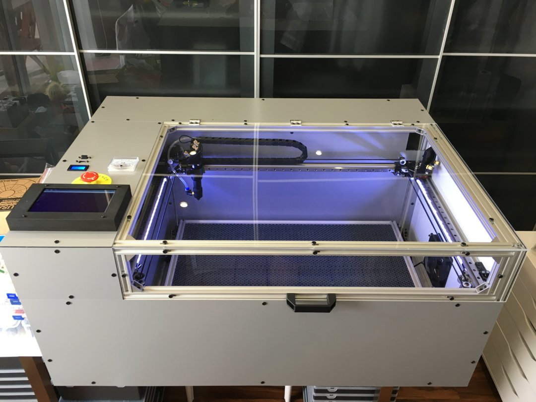
Complete machine :
"Naked" machine without inner and cover plates :
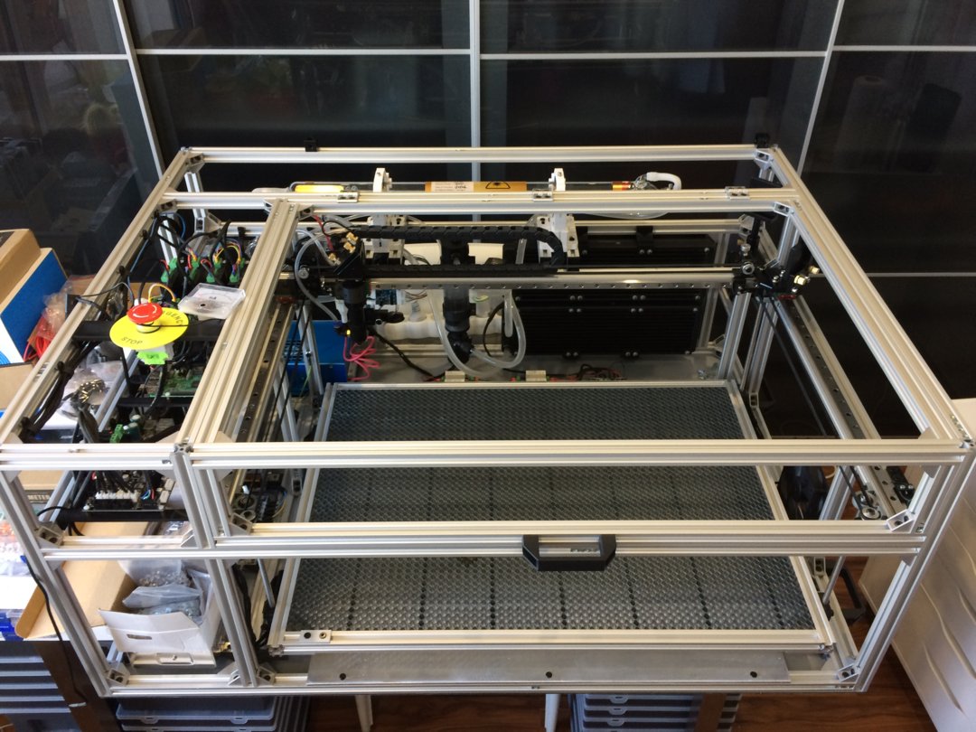
The basic idea was to build a frame and motion system using as much of standard/stock parts as possible - no custom plates. Despite having cnc milling machine at home I wanted to avoid those because of limited experience of machine building which in my case sometimes means trial and error. Of course I wanted to save some time and resources as well. So everything what is out of aluminium is standard stock and all the custom parts are 3d printed (STL files for these printed parts are uploaded in Files section).


The basic frame is build out of v-slot linear rails, mostly 2020 and few 2040. I used the service of custom cut lengths of v-slot when purchasing (thank you Ooznest!!) as I would never cut them witch such precision in reasonable time and price. In Files tab you can find .skp file which is also a part list for those rails. The frame is assembled using a lot of aluminium corners and even more 5x8 low profile screws together with sliding t-nut blocks. I used t-nut blocks rather than drop-in or those flat slide-in nuts to ensure the frame is rigid enough. It is hassle with those slide-ins, you always forget to put some somewhere;-) Anyway the approach of using t-nut blocks payed off - me and my friend were moving the machine after it was finished - two floors, car transport, another stairs and no mirror disaligment even a fraction of mm


First thing after building the frame was to attach the bottom cover panel and only after that continue building. Just because when something drops you don’t have to chase it on ground;-) For the bottom and all the other covering panels I have used aluminum/pe composite panels which seems to have good rigidity/weight/price/appearence factor. Those panels I have sourced from local supplier also already pre-cut. Holes for fans, controls, displays etc. were cut on my cnc router. The lid is than covered with polycarbonate panel. Original idea was to apply IR blocking foil to that lid to absorb possible reflections. After performing some tests with used polycarbonate I consider that unnecessary.


The motion is accomplished with belt system for X and for Y axis and leadscrews for Z axis. For all axis I have used NEMA 17 as the system is generally leight weight. On X and Y there are linear rails with MGN12H carriages, those are some generic chinese ones and works just fine. Z axis movement is accomplished using 4 motors and closed loop belt transmission to leadscrews. It would be easier and more elegant to have motors directly fitted with leadscrews, however I had those classic around. Those 4xNEMA 17 easiky hold and move the honehcomb table. Each motor has its own external driver with one spare fitted in case of failure and easy replacement. Every axis is fitted with min and max enstops just to be sure not to damage the machine by itself (or dumb operator;-) )


Safety switch on cover lid is installed as well :

The honeycomb table is one of my favourite and the one I’m really proud of


The cooling system of CO2 tube consists of 6x24V fans with high volume flow and two radiators originally used for computer water cooling. These are connected with water pump and water reservoir and the tube itself. The air flow is routed (will be after placement of inner cover plates) from the outside of the machine, than through the back side with tube, later left side with electronics and through the top slot where the cable chain of Y axis is to the cutting chamber. Finally it is evacuated with the help of one extraction fan on the right side. This setup should help electronics cooldown and smoke/fumes extraction without contaminating anythig else than cutting chamber. I had a ten minutes test run at 100% laser power at room tempearure of 24C with an increase up to 27C which I consider as acceptable cooling - specs of my tube say to keep it below 30C and when finished it will be placed in garage where is a stable temp of 19C. All the fans are switched on/off through external SSR despite the control board’s mosfets should be capable to handle them. In the end I have removed those dust grids covering the fans as it looked that it limits the airflow more significantly than expected despite it didn't seem to affect cooling perfomance in any way.


So far the machine is fitted with generic 700mm chinese CO2 laser tube rated to 40W with appropriate high voltage PSU sourced from Cloudray. It works like a charm! The upgrade is possible up to 800-850mm tube without modifying the frame. Large tube can be fitted after frame extension with a few of v-slot segments. There is enough space for larger PSU if needed. Wiring of PSU control needed to be done through level shifter as the control board has 3V logic and PSU accepts 5V input for PWM control.


Laser mirrors and laser head where also source from Cloudray and can be adjusted according to the machine needs without any further modifications. Laserhead is supplied with air from high volume brushless blower fan with its own driver. It is fed to the laserhead with silicone tube which is stored together with wiring in cable chain and so far it seems it produces a fair amount of airflow.


For electronics there are in total 3 PSUs. One for high voltage obviously, second DC24V for high current appliance - motors and fans and third one dual output DC5V12V for raspberry pi and control board. The control board is MKS Sbase v1.3. I know it is not original and I know it is not opensource board. Anyway I have donated Smoothieware and I do support opensource and makers throughout different projects. After some testing one unexpected problem arised. Despite those PSUs seems to be good quality and deliver what they are rated for, they were pretty cheap and does not have soft start. Charging their capacitors require high peak current and from time to time they trip the 16A braker. So I have attached current limiter with PTC thermistor.


Beside the controller itself the Raspberry Pi 3B+ is fitted as well. It runs Raspbian configured to either connect to know WiFi network or if not found to create a hotspot. This ensures that the machine can be connected anytime. On the Raspberry there are installed bCNC, LaserWeb, Printrun console to provide various means of control. Of course it is connected to the controller via USB and additionally to 7 inch touchscreen.

I don’t plan to put together a complete part list only to be here, it would be so time consuming. However if you want some more information about the build, parts or anything just drop the message in the discussion and I will try to reply/upload whatever helps

LS-LASER
Build in 'Laser Cutter Builds' published by LukasK, Oct 3, 2018.
I have completed some custom build 3d printers (i3 and delta style) and a cnc mill based on v-slot and c-beam. From the beginning the cnc was built to fit/change between router, 5w led laser module and plotter pen. While all three works great, the build is primarily focused on heavy duty milling and brings some disadvantages when it comes to laser - slow because of leadscrew motion system and not as powerful because of “only” led laser. That is why I have started this build of co2 laser machine.
-
-
Build Author LukasK, Find all builds by LukasK
-
- Loading...
-
Build Details
- Build License:
-
- CC - Attribution NonCommercial - Share Alike - CC BY NC SA
Reason for this Build
I do it because I can, I can because I want to, I want to because they said I couldn't ;-)Inspired by
-
Attached Files:
-


