I stripped my original 3d budget printer for the table and electronics.
Other than the table and motors and ramps board, and extruder, this was all openbuilds material.
I started out with 4 "Linear Actuator Bundle(Lead Screw)" kits for the axis. I quickly found out that lead screws are not a good choice for X and Y axis because it had to move way to slow without it loosing steps. So i replaced the X and Y axis lead screws with belts.
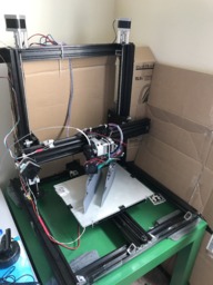
As you can see in the picture, I then constructed a simple square frame and mounted the Y axis to it, and the 2 Z axis to it. The X axis got mounted to both the Z axis Lead screw kits.
Its a very simple build, provides very good print quality when close to the table, but begins to have some obvious loss in quality when the Z gets higher because I really dont have anything supporting the Z axis column. Its pretty ridged in and of it self though, so I am pretty happy with it.
I am looking to build a CoreXY machine and use these parts from this printer in hopes of getting faster print times, and getting away from the table moving.
To build it yourself.
Step one: I created the square base using the 20x40x500mm rails. All rails are fixed together using the 90 deg angle brackets.
Step Two:
I attached the two Z-Axis columns to the base using the same angle brackets. Its offset from center, pushing more towards the back of the printer because the extruder and X-axis stick out a bit from the Z-Axis columns.
Step Three:
I attached the Y-Axis to the base, positioning it center left to right. Secured down again with these angle brackets.
Step Four:
I attached the X-Axis to the two Z-Columns as shown in this picture:
This is actually looking down onto it from the top. Its mounted directly onto the stock Leadscrew kit sold by OpenBuilds. Pretty basic, pretty chepo. I should have done a better job, but I was in a rush, and it actually does works pretty well.
Step Five:
Getting the X and Y axis to run on belts and not lead screws.
I had to go belts because the slowness of lead screws. Fine for Z-axis, but not fast rapids with X and Y. I purchased some idler rollers from openbuilds and attached them to the ends, and removed the LeadScrew End plates that came with the stock leadscrew setup. You will notice in the first image, the Z-axis have a plate mounted on the top and bottom to secure the stepper and leadscrew bearings. These are the plates I removed.
I had to also mount the steppers perpendicular now to the axis and not parallel so the belt can run properly. After some thinking, I decided to use one of the existing plates for the steppers, and just mount them on its side like in the first image. You can see from the Z-Axis steppers, they are mounted straight up, and have long spacers.
I had to shorten the spacers, and cut the screws so the stepper gear would line up with the idler pulley.
Both X-axis and Y-Axis are identical, they have been both modified from the original LeadScrew Kit, and turned into belt driven.
Step Six:
Mounting the extruder to the X-Axis.
This was a bit more of a pain then I liked. You cans see it is mounted to the basic plate from the kit. There was a file on thingyverse for these extruders. It was designed for obviously not this printer, but the top section worked as a clamp and I was able to print that part before I tore apart my other printer.
The main part however was a custom made piece from an aluminum block I had made at work. Its a custom, one of a kind, but it could be printed, and I will put in the link for it when I submit it to thingyverse. Here is a link to the original files from BondTech that may work on others builds: Mounts - Bondtech AB
Step Seven:
Mounting the table, Wiring it all up, and testing.
After I got it all wired up and tested it, I had no where to place my limit switches, so I designed these guys that mount right on the rails: v-groove limit switch braket by changedsoul
Ill post a link for these too if anyone would like to use them. They work surprisingly well.
I could not get a good pic of the plate the table it mounted to, but its the Build Plate located here: Build Plate
This place had holes that lined up great with the plate on the Y-Axis. Some short spacers are needed to lift up over the Y-Axis plates screws, but once the Build plate is attached, the heated bed is a perfect fit.
First Ever Build
Build in 'X/Y Table Style Bots' published by changedsoul, Sep 6, 2017.
This is my first attempt at building my own 3d printer.
-
-
Build Author changedsoul, Find all builds by changedsoul
-
- Loading...
-
Build Details
- Build License:
-
- CC - Attribution - CC BY
Reason for this Build
My Original 3d Printer was all plastic and very poor print quality -
Parts list
Qty Part Name Part Link Comments 4 V-Slot® NEMA 17 Linear Actuator Bundle Lead Screw http://openbuildspartstore.com/v-slot-nema-17-linear-actu... Link 5 20mmx40mmx500mm http://openbuildspartstore.com/v-slot-linear-rail/ Link 2 Smooth Idler Pulley Wheel Kit http://openbuildspartstore.com/smooth-idler-pulley-wheel-... Link 16 Cast Corner Bracket http://openbuildspartstore.com/cast-corner-bracket/ Link 1 All metal Hotend from E3D http://www.matterhackers.com/store/l/v6-hotend-full-kit-1... Link 1 Bondtech QR Universal Extruder - 1.75mm http://www.matterhackers.com/store/l/bondtech-qr-universa... Link 1 Build Plate http://openbuildspartstore.com/build-plate/ Link


