
The Slider
The actual slider is a very simple design for this Mk. I version. I'm not going to go into the intricate details because of its simplicity, but this is it:
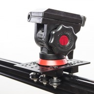
1500mm of black anodised 2040 V-Slot with actuator end mounts on each end. The dolly is a regular V-Slot gantry plate with 6 Delrin Dual V-wheels, eccentric-spacer'd on one side. Simple!
If for some reason you need a full explanation with all the whys and wherefores, I did an article/video on it on Tuts+.
A future Mk.II version would most likely be more of a box shape, with two parallel 2020 V-Slot rails a few inches apart with the gantry wheels running on the inside, and perpendicular end brackets holding the motor and stuff. One specifically designed only for time lapse and not video could use a screw drive rather than a belt drive, and save motor power.
Automation!
There are two parts to the automation process; retrofitting the slider & assembling the hardware, and actual programming.
Slider Retrofit
Retrofitting the slider simply consists of adding an OpenBuilds NEMA 17 stepper motor and a 20x2mm pulley to one end, putting a smooth idler pulley on the other (not so easy within the confines of an actuator end mount, there are much more practical solutions, but I was going for aesthetics as well), and stringing a GT2 belt between them!
It's pretty difficult to get the idler all spaced out and tightened up in there, but some bent nose pliers and patience will go a long way. Alternatively, just use a regular end mount which allows access!
Feeding the GT2 belt through the centre of the V-Slot was much easier than I'd envisaged, it's far lower friction on the anodisation than you'd think, but still plenty grippy in general.
Getting the NEMA 17 on there was super easy; just slot the shaft into the side of the Actuator End Mount while holding the pulley inside the mount. I found that having the smooth spacing/set screw holder on the pulley opposite the motor allowed easier alignment with the centre of the V-Slot. That doesn't actually make any sense since the End Mount is symmetrical, but there you go.
Don't tighten down the pulley just yet; first attach the motor with the 4x45mm M3 bolts, ensuring that you don't overtighten any of them and prevent the face of the motor from sitting flush with the round face of the End Mount. Once that's done and your bolts are all tightened up with the motor sitting flat against the mount, you can tighten down the pulley while keeping the centre of the teeth aligned with the V-Slot.
Finish stringing together the timing belt and you're done. I had to ziptie since the Parts Store didn't have any crimp clamps in stock when I ordered, but no big deal.
Automation Hardware
I'm not going to go into too much detail here, since for most builders it should be relatively basic stuff, but essentially we're taking the electronics parts and assembling them into the following diagram:
I go into this in a whole lot of detail right here in the second Tuts+ write up, if you need it, but simply plugging the stuff together (and soldering on the A4988) should do the job:
Programming
This is where it gets more complex, though at least most of the hard work is done now! I designed and coded a calculator, controller and GUI sketch for the Arduino Uno, which can be found in its relatively rudimentary but entirely functional form on GitHub here.
This sketch is explained in some detail in the second Tuts+ article just above, though I built it modularly with a fairly defined flow, so it should be simple enough to follow.
I think of it as a scratch-built one-axis CNC controller... Which kinda makes me want to try to scratch-build an entire actual 3/4/5-axis CNC controller. But anyway!
The result of that programming is what I relate over an only-semi-meandering 15 minutes here:
...The other 5 minutes or so are talking about the slider in use, building a simple 5-minute plywood case for the 12V adaptor, and a couple of example videos. There's another example here, which I can't remember if I added to the main video or not:
Conclusion
Not bad performance, I think it would be improved with some deflickering software and some more solid legs for the slider itself. These could be simple plywood stands at each end, though some folding aluminium legs and some rubber feet would be nice. There doesn't seem to be a straightforward OpenBuilds/80/20 type solution for all-terrain support (naturally!), I think it would be a custom build for those. But I don't yet have a CNC mill, so it'll have to wait.
This is just the Mk.I version, designed to have as low a pricepoint as possible without sacrificing too much professional aesthetic. Originally my idea was based around EMT conduit, but I think V-Slot worked much better (and is far more plug-and-play for inexperienced builders). The Mk.II version would/will take into account lessons learned here, and be a two-rail version with interior wheels like I mentioned above. This would look better (like the Kessler CineSlider), reduce the likelihood of dirt ingress, and eliminate the need for awkward eccentric spacers, as the rails could be precisely aligned with end-brackets and medial support spacers. It would also be self-supporting except perhaps with larger telephoto lenses.
Not sure what else to put in this writeup that isn't already in those hefty videos/articles, so if you have any further questions, fire away!
DSLR Video Slider
Build in 'Camera Sliders - Rigs' published by Rob Taylor, Aug 31, 2014.
A simple 1500mm V Slot camera slider for timelapse and possibly video with an Arduino Uno controlling a Pololu A4988 driving an OpenBuilds NEMA 17 stepper, and triggering the camera.
-
-
Build Author Rob Taylor, Find all builds by Rob Taylor
-
- Loading...
-
Build Details
- Build License:
-
- CC - Attribution Share Alike - CC BY SA
Reason for this Build
I wanted to experiment with OpenBuilds hardware in a simple way before diving into the 3D reprap/fab stuff. And I'm a photographer. So a 1-axis camera slider made a lot of sense!Inspired by
![[IMG]](proxy.php?image=http%3A%2F%2Frobtaylorcase.com%2Fblog%2Fwp-content%2Fuploads%2F2014%2F08%2FMG_1457_sm.jpg&hash=4ae909118d7efb6f2b8b5820095aeb98)
![[IMG]](proxy.php?image=http%3A%2F%2Frobtaylorcase.com%2Fblog%2Fwp-content%2Fuploads%2F2014%2F08%2FMG_1454_sm.jpg&hash=7481337f344c29373dea5d3145f791a7)
![[IMG]](proxy.php?image=https%3A%2F%2Fcms-assets.tutsplus.com%2Fuploads%2Fusers%2F148%2Fposts%2F21539%2Fimage%2Farduinostepper_03.jpg&hash=60ebf0b4b862ed23c8406ff8eeaba4ef)
![[IMG]](proxy.php?image=https%3A%2F%2Fcms-assets.tutsplus.com%2Fuploads%2Fusers%2F148%2Fposts%2F21539%2Fimage%2Farduinostepper_04.jpg&hash=dbba9c90e2ce2749badaf1a7a354c20f)
![[IMG]](proxy.php?image=https%3A%2F%2Fcms-assets.tutsplus.com%2Fuploads%2Fusers%2F148%2Fposts%2F21539%2Fimage%2Farduinostepper_02.jpg&hash=b0bd9177db244dbe1e20875d74d5f09f)
![[IMG]](proxy.php?image=http%3A%2F%2Frobtaylorcase.com%2Fblog%2Fwp-content%2Fuploads%2F2014%2F08%2Farduinostepper_01.jpg&hash=42646ff9874f531a1029b9fa8e560b77)
![[IMG]](proxy.php?image=https%3A%2F%2Fcms-assets.tutsplus.com%2Fuploads%2Fusers%2F148%2Fposts%2F21539%2Fimage%2Farduinostepper_09.jpg&hash=5930b626252f1ba69cff7f245af3809b)