
So the purpose of this build is to create an economical and robust PCB milling solution, with the versatility to be adapted to a 3D printer or perhaps a laser engraver. I have to give a shout out to @HenryCNC , because although I didn't design my machine off of his/hers, I did look to the Desktop CNC as another perspective on a similar problem. My design criteria are as follows:
1. Should be the smallest form factor to mill a PCB at the maximum envelope of the free version of Eagle.
2. Should be able to be 3D print a similar build envelope to a M3D printer.
3. Should cost as little as possible and no more than the C Beam Machine Mechanical Bundle.
**4. Should be able to be made with as little tooling and no major modifications to the parts from the store. (ie cutting to a special size or modifying a bracket...filing to true is ok)**
This first concept costs about $450 US, although I could reduce the cost but changing out some of the 40mm X 40mm stock for 20mm X 40mm. I think i could have benefited from making the Y axis a 500mm CBeam, but part of the design was to try and be as compact as possible.
If you look at this concept and notice anything you think is a glaring omission (besides the makerlink and corner brackets) please feel free to comment your suggestions as I want to make this build a capable but accessible design.
UPDATE 2/1/2017:
Alright. First parts in and the frame is assembled. So far it has taken about 45 mins to put together, although if I hadn't taken it apart 3 times I would have only been about 20. The most important thing I can mention here is that we are going to use the 90 degree hidden brackets in an new and interesting way (or at least a way I haven't seen). We are going to add some sneaky ninja support to all the joints because we are using 40X40.

You will notice that I am using one of the pairs of hidden 90s so that they affix to the beam under then column that they will be supporting. This is only possible because the profile is 40mm wide. Note that if you do this you have to position and tighten down the bottom set screws or you won't be able to do that when its on. (Take apart #1 of 3....lol)
I doubled these in response to the profile wanting to deflect by bending the hidden 90. While they won't bend if in a square frame or doubled normally, the single 90 unsupported wanted to bend away from the base profile.

I have to get longer set screws for the reversed brackets and I don't have all my brackets in (half are coming in with the C Beam Parts), but once I do I can tell this will be a rigid setup. I will eventually go into some other design considerations but in the interest of not overwhelming this update I will press on.

This is good as a size reference as well as a overall shot. Look in the files section for more. As soon as I have more I'll let you know.
As a quick note I will say that if you mounted a router or spindle that fit the OpenBuilds spindle mount one would be able to complete this design with only hex keys and a wrench. Something that I would like to see is a starter machine that can grow as the users abilities and budget allow. This has been set up to allow a conversion to 3D printing, which can help justify the cost as a multi-role machine.
I look forward to your feedback!!
-PhotoSgt85
UPDATE 2.2.2017:
So I ran to Lowes today and cleared them out of their supply of M5-0.8 8mm setscrews. After mounting them (only had 12) I can tell you that having the 4 90's per joint is extremely rigid. I currenly left the screws at 8mm but i will eventually bring them down to 6mm on the disk sander. While it wont change the functionality I really don't like the look of the excess screw on the project.


-PhotoSgt85
UPDATE 2.6.2017:
Progress, a missed design goal, and other fine adventures....
So there has been some progress on this build. My toddler decided that he wanted to help and with a breadboard, several tactile buttons and a wrench he managed to complete and mount the X axis. (Ok, so he pressed some buttons and tried to figure out why the carriage moved when he spun the lead screw) Honestly my best moment building yet....
So as I said the X axis is mounted and when I took a closer look at the CBeam gantry I discovered that it was not 90 degree mountable like the XL version. That is until I got back to work...Drilling out the square pattern threaded holes with a 13/64" drill bit (~.203 in) I could pass an 8mm M5 low profile bolt through and thread into the opposing plate, but I would be left with the head of the screw sitting proud of the surface.

Next up 3/8" end mill. I counter bored on the drill press by eye, which worked but was so ugly that a real machinist would have committed Seppuku...(this i did not take a photo of on purpose)
Next I attached all the wheels and antibacklash nut and mounted the two plates together. Reassembled the Z axis and presto :

Now this brings me to my failure in that I could not design this to be completely unmodified from what you order, and that makes me a little sad. I am going to try and cut some plates on the XL and see if I can't improve my overall design. That being said so far this can all be done with a drill press, or hand drill if you are more competent than I. I'm not sure that you need to recess the screw, but if you needed to you could accomplish this with a 3/8 drill bit in lieu of the end mill.
I have the Y axis mocked up for pictures but I have another order to open builds for some more hardware before that is complete. When this is up and working I will be revising the plans to different versions, each with a different focus (ease of build, lowest cost, most utility...ect)

Thoughts? Feelings? Advice? I look forward to it all.
-PhotoSgt85
UPDATE 2.7.2017:
Just a quick update that a .step file was added containing the modifications described above.
UPDATE 2.14.2017:
Happy Valentines Day everyone! I hope that all is well for you. Quick side note off topic, my personal computer's SSD decided the day had come to give up (it was only 6 months old). Fortunately it was under warranty yet, so replacement should be around soon. Until then I will have to limit my posts to what time I can spend on my wife's laptop.
So on the new photos I posted I am showing 4 TB600 stepper drivers and a CNC Shield V3 nestled snug within the lower base of the Desktop PCB mill. Unfortunately the power supply can't fit in there as well, but what are you going to do? I am thinking of trying to find an inline power supply like you would find in a laptop charger as I think I remember seeing a 24V one with around 20A. Not positive so don't quote me. Anywho, I realize that the TB6600 do not have the best reputation but since the actual strain on this machine should never be more than the milling of a PCB the inertial loads present should be the most I have to worry about, and if that is the case I can ensure that I have the microstepping adjusted so I stay well within torque curve. The fourth driver is for the extruder I will eventually fit to this machine to make it a mini 3D printer. The images are uploaded to the files section as they are not on this computer. I have a few other pressing projects to get to for the next week or so and then I am hoping to complete this build after that. Thanks!
-PhotoSgt85
UPDATE 2.17.2017:
I received the remaining parts today from open builds which allowed me to complete the mechanical portion of the build except for the bed. I was waiting on my laptop coming back in from service as the SSD failed on the last one. I guess its good that I dont keep anything on the device that isnt backed up.
So here are some pictures of the complete mechanics with the Y axis tightened on it. I have to now get the bCNC to GRBL (Arduino) figured out a little better as I keep having bCNC throw error 1 and 22 when I try to run stuff. That being said, I haven't run anything out of inkscape or Fusion 360, only build in stuff from bCNC and some small part files from the XL, which is running a smoothieboard.


As you can see above I was planning on packing the electronics into the base and wiring it all together but I have since decided that given the wiring required it will be easier to wire it outside for now and then cut a PCB (would it now be a MCB?) and have the signal and power distribution handled through that. Other than that I think that this system will be a great addition to my work space and opens a lot of designs that I want to do that would be impractical any other way. I have a video I have to upload if I can get to it but for now if you have any questions please let me know, otherwise Ill post again when I start cutting on this thing...or once I design and cut the dremel holder.
-PhotoSgt85
UPDATE 3.1.2017:
So after a whole week of the flu I am finally getting back into the swing of things enough to post what I believe will be the final design. I have all the parts on order from the parts store and will soon update the BOM with the final total and most importantly final cost. The bed material will be something of a conversation as its material will be driven by the function you are doing. I have updated the main image and will put a copy in the files section, but in looking around at other builds I have seen a Dremel mounting solution on the Routy GT2 290 that really struck me as a potential solution, especially considering that the forces seen by the mount should be minimal relative to what would be seen in a normal CNC operation. I look forward to hearing feed back and once done and tested will begin a build manual and will then include all the files I can generate.
-PhotoSgt85
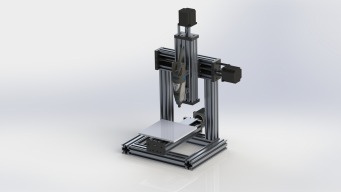
Desktop PCB Maker
Build in 'X/Y Table Style CNC Mill' published by PhotoSgt85, Mar 1, 2017.
With the focus always on larger builds I wanted to focus on a desktop PCB milling machine that fulfills the average users desktop needs at an entry level cost. Design considerations will allow expandable capabilities to include 3D printing and any other functions a small form Cartesian robot can perform. The current iteration has a desktop footprint of approximately 15.5" X 14.5".
-
-
Build Author PhotoSgt85, Find all builds by PhotoSgt85
-
- Loading...
-
Build Details
- Build License:
-
- CC - Attribution - CC BY
Reason for this Build
I want to make a good desktop PCB maker with eventual 3D printing capabilities that provides reasonable cost of entry but then have the ability to be upgraded readily as many people don't have the money to do these things all at once or the space to accommodate many different machines. -
Parts list
Qty Part Name Part Link Comments 6 40mm X 40mm X 250mm VSlot http://openbuildspartstore.com/v-slot-40x40-linear-rail/ Link 3 250mm C Beam Linear Actuator Bundle http://openbuildspartstore.com/c-beam-linear-actuator-bun... Link 4 MakerLink 90 Hidden T Nut http://openbuildspartstore.com/90-hidden-tee-nut-makerlin... Link -
Attached Files:
-


