Welcome to Our Community

Some features disabled for guests. Register Today.

The MULE (an OX inspired 3-axis CNC)

Discussion in 'CNC Mills/Routers' started by Jason Kraft, Jan 15, 2016.
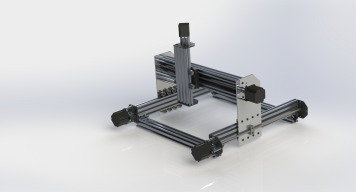
  1. Jason Kraft

    Builder

    Joined:
    Jan 10, 2016
    Messages:
    10
    Likes Received:
    4
    Jason Kraft published a new build:

    Read more about this build...
     
    Tom Allen likes this.
  2. Florian Bauereisen

    Florian Bauereisen Well-Known
    Builder

    Joined:
    Feb 24, 2014
    Messages:
    188
    Likes Received:
    60
    Hi.
    Cutting through materials like aluminium?
    I really doubt that- sorry to say so.
    Your (not existent) machine bed or rather whimpy frame will flex like rubber, 2 leadscrews instead of belt - no matter.
    The x and y of the frame not even beeing in one plane of work, with no bracing to speak of and no aditional extrusions preventing flex -you will be lucky to cut soft wood.
    Sorry to say so, but the machine is missing even the basics.

    Even if you are able to "pulverise" a little alu or scratch it you won`t be cutting or milling (producing chips) with such a machine.
    Without a machine-bed to speak of your machine will vibrate adding not only to toolmarks on cutting faces sideways, as well to slip-stick on surface milling and will cost you a lot in broken bits once trying to use smaller sices of them.
    If milling out of center it will be turned into a parallelogram and you are going to be lucky not to break it.

    To save you a lot of grief and frustration: back to drawing board and try again.

    In order to have a sturdy machine it goes like that:
    without a sturdy and heavy machinebed your machine will vibrate and "wander around" while cutting, prevent the machine to become a parallelogram - so that is number one.
    Gantry needs to be stiff enough to not flex when z colum is accel- and decellerated as well if cutting forces try pushing the milling bit away from sidefaces (on aluminum for ex) so sideplates need to be stiff.
    Z colum is an often overlooked part too.
    It may flex left to right , back and fro, and beeing "pushed up" while trying to push the bit down into the part to be milled.
    Aditionally all these three forces on the z-colum also transfere into the x-extrusion.
    So a tall but "slim" extrusion on x may be twistet back and fro by z pushing downwards...make that part tall and wide.
    Your cut would not have vertical faces.

    Have a look at other designs, preferable watch vids of them cutting aluminium (if that is what you are after) and compare build and results.

    you will soon see the difference

    To give you an impression:
    I guess my x- gantry alone weights twice your whole machine but i would not try to save any weight on mine
    CIMG3911.JPG
    CIMG3960.JPG


    Might sound harsh but i only try to help here, do not take that personal please.

    greets

    flo
     
    #2 Florian Bauereisen, Jan 16, 2016
    Last edited: Jan 16, 2016
  3. Florian Bauereisen

    Florian Bauereisen Well-Known
    Builder

    Joined:
    Feb 24, 2014
    Messages:
    188
    Likes Received:
    60
    BTW
    this machine is designed to take "ony" the forces of a 800w Spindle and using 6mm bits in aluminium max and taking it easy while doing so (rarely need to mill alu - time is not important ) ...
    If i would think about using a 2KW spindle i would have designed a lot more sturdy.

    Flo
     
  4. Jason Kraft

    Builder

    Joined:
    Jan 10, 2016
    Messages:
    10
    Likes Received:
    4
    Thank you so much for your feedback! As someone who has never made anything like this before, I really appreciate any sort of help. After looking back at my design, your points make a ton of sense. I'm thinking I should add some braces along the bottom to add some rigidity to the Y-axis as well as to provide a spot for the machine bed to rest on (I was thinking of using a couple layers of 1/2" MDF for a simple bed). I had a 20x60 V-slot behind the C-beam on the gantry, but I think I might move that to improve the strength of the X-axis. Not sure yet what I will do to improve the Z-axis.

    For the gantry supports I was originally going to use 3/16" thick aluminum since that was readily available at my local store and it was pretty cheap, but would you recommend that I go for something thicker?

    Ultimately, milling aluminum may be too lofty a goal for now. At the moment I'd like to at least mill wood reliably on a limited budget.
     
  5. Florian Bauereisen

    Florian Bauereisen Well-Known
    Builder

    Joined:
    Feb 24, 2014
    Messages:
    188
    Likes Received:
    60
    Hi,
    an easy way to improve strenth of a part is to bolt on a simple l-shaped aluminum . Helps heaps , costs little.
    Why is that so ?
    same as in every other design ( railroad rails, building skyscrapers) try to build I-Beams. It is more rigide for the same amount of material used to space two flats as far appart by using an "I" between than to simply add thickness.
    If one does look closely our machine bed is an I-beam layed flat. At least if one builds a ladder frame style bed.
    So just bolt anything aluminum in between your bed to stiffen up.
    An L-bracket or two onto the back of your x too.
    The side plates could easylie be strenghtended by bolting on either l-brackets or, like i did some sqare stock ( but my sideplates are made of 20mm to start off and beeing braced on the other side too).
    Best would be to make a sandwich of two plates either side spaced appart using some square material...

    None of these mods would break the bank and materials should easyly be accessible. ( doubling your sideplates -you do not need cnc´d sideplates... use existing ones as drilling guides on simple square parts...)

    Z- can be improved too.
    Simply by gometry.
    first off - run your z-plate ( the one that ataches z-colum to x) with the weels on top and underneath x.
    That improves accuracy simply by spacing appart
    Imagine something like this:
    if your setup has a "play" of say 0,1mm (wheels running in extrusion...) than a distance of 10 cm might result in a pivoting action of say 1 deg.
    Now spacing same setup 20 cm appart your pivot results in only 0,5 deg.
    Doesn`t sound a lot but by lowering your z-colum the lever will lenghten again (0,5 deg. along say 3cm vs. 18 cm)

    Same for the z-colum
    build a taller and wider plate to transfere the loads and play onto a bigger space giving better lever.
    Adding l-brackets all along will prevent the now bigger parts to flex.

    To improve accuracy you could further either shorten sideplates (less z - so less lever of milling bit to z-plate) or at least raise your material to be cut as high as possible while cutting aluminum...

    All of the mentioned hardly costs a lot, it is about how to use material not how much..

    hope that helps

    flo
     
    #5 Florian Bauereisen, Jan 16, 2016
    Last edited: Jan 17, 2016

Share This Page

  1. This site uses cookies to help personalise content, tailor your experience and to keep you logged in if you register.
    By continuing to use this site, you are consenting to our use of cookies.
    Dismiss Notice