Welcome to Our Community

Some features disabled for guests. Register Today.

H-Bot CoreXY Cube with Fixed Build Plate-

Discussion in '3D printers' started by TomH, Apr 3, 2015.
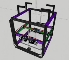
  1. TomH

    TomH Well-Known
    Builder

    Joined:
    Mar 10, 2015
    Messages:
    108
    Likes Received:
    11
    TomH published a new build:

    Read more about this build...
     
    #1 TomH, Apr 3, 2015
    Last edited: Apr 10, 2015
  2. TomH

    TomH Well-Known
    Builder

    Joined:
    Mar 10, 2015
    Messages:
    108
    Likes Received:
    11
    For those that saw the earlier design, I moved the extruders to the gantry to minimize bowden tubed length. This will also add to inertial mass which will further offset/limit gantry movement inertial response. The other greatest change was moving from double to triple v-slot rails on the gantry and on the vertical braces. This change will also add significant inertial mass while also adding stiffness to both the gantry and frame. It also dispensed with 4 triple hole joining straps, 4 angle brackets, and four double angle brackets (which will be replaced by less expensive, non-OB single brackets). So all-in-all the change was actually a wash cost-wise and it simplifies the structure. It also allows the top frame rails to be turned flat, further enhancing frame stiffness and racking resistance. In the front and rear, the triple rail also allows for an enclosure to be implemented by simply sliding a sheet of your desired material (lexan, etc.) into the v-slot! As you can see it also allowed me to place the Z-steppers back on the bottom, lowering the CG and ultimately placing them to be hidden and below a to-be insulated and closed off bottom area where the power supply will be (a single 24V supply as I will be using a 120V heater).

    I also changed the gantry to a single rail, reducing mass (for added speed) and optimizing the CG. This also let me switch to a standard 20mm v-slot gantry plate which, with only minor modification can be used with mini wheels and will allow the e3d chimera (cyclops pictured - need to find a model) to be directly mounted underneath - reducing wasted build-able area! This will also allow a PLA cooling fan to be mounted underneath without impact build area - double win!

    Finally, I moved the filament holders on the top so that they can either be inside or outside of an enclosed cube (as desired). Their placement also allows the filament to be fed from the spool through a very short piece of 2x4mm PTFE tube directly into the vertical rail! Another small section of PTFE (which is perfectly sized for the center hole in a v-slot rail) will be used at the bottom rail exit (this one will need to be chamfered at the opening to allow easy filament insertion) and up through the bottom board.

    As noted previously, this build allows simple expansion to quad extruders with no modification and no impact to build area!!!

    Any thoughts on the new model???
    screenshot_15.png
    screenshot_16.png screenshot_17.png
     
  3. Dennis Cao

    Builder

    Joined:
    Nov 9, 2014
    Messages:
    3
    Likes Received:
    0
    will your z be overconstrained with all the wheels on vertical rails? and it might be worth going to a triple lead screw z axis
     
  4. TomH

    TomH Well-Known
    Builder

    Joined:
    Mar 10, 2015
    Messages:
    108
    Likes Received:
    11
    What do you mean by overconstrained? Binding issues? The wheels are there to limit Z axis wobble. Are you suggesting a triple lead screw with no wheels? If you look back from where I started, http://www.openbuilds.com/threads/h-bot-corexy-cube.788/page-2 #53, I have designed in the ability to move to 3 or 4 lead screws but I am still not sure I need to. As long as all of the tolerances are good, there shouldn't be a binding issue. If it turns out to be a problem, I will probably just go to 4 leadscrews instead of 3. I am trying to be just as cost conscious as I am robust. Do you think the overconstraint issue is insurmountable without moving to 3 or 4 lead screws?
     
  5. Dennis Cao

    Builder

    Joined:
    Nov 9, 2014
    Messages:
    3
    Likes Received:
    0
    Ah I missed the discussion in the other thread, obviously you've considered those problems already.

    Full disclosure: I'm still waiting to build my own corexy printer, will go with either your design or the triple c-bot. I'm curious to see if the moving gantry will present any problems!
     
  6. Carl Feniak

    Carl Feniak Journeyman
    Builder

    Joined:
    Mar 18, 2014
    Messages:
    654
    Likes Received:
    246
    Interesting, make sure your filament spools spin very easily or there will be variable pressure on one of your Z flexible couplings as the moving filament drives pick up and release tension to spin the spool. Could lead to Z artifacts.
     
  7. TomH

    TomH Well-Known
    Builder

    Joined:
    Mar 10, 2015
    Messages:
    108
    Likes Received:
    11
    Thanks. I'll definitely be paying close attention to the freedom of the extruder feed from the spools.
     
  8. TomH

    TomH Well-Known
    Builder

    Joined:
    Mar 10, 2015
    Messages:
    108
    Likes Received:
    11
    Ok, I think it's about time to stick a fork in it! I managed to further balance the CG of the X/Y gantry and after much entering review, I have gone back to a 20x40mm carriage and changed the wheels to mini v's all around. With an effective 4 linear rails in addition to the Z screws, it should be quite solid for the moving mass of the gantry. I think I have also managed to squeeze the full 400x400x400mm print area out - though I will likely have to wait for actual build to fully verify. I also managed to retain all openbuilds components with the exception of a printed part for a quick release for the extruders. This setup also allows greater hotend surface area contact with the gantry plate which should greatly aid cooling.

    Please take a look and provide any last critiques before I finalize the BOM and complete my parts orders. Please note, though I have depicted where two additional extruders/hotends would be placed, I only plan on beginning with a double setup (with the exception of the main frame/spool holders which I will add for symmetry as it will only add about $11 to the build).

    screenshot_21.png screenshot_22.png screenshot_24.png
     
    #8 TomH, Apr 7, 2015
    Last edited: Apr 13, 2015
  9. adamcooks

    adamcooks Well-Known
    Builder

    Joined:
    Nov 6, 2014
    Messages:
    244
    Likes Received:
    65
    I would think that rotating your gantry plate to vertical would more easily facilitate both the clamping of your belt and the mounting of your hot end.
     
  10. WayneHunter

    Builder

    Joined:
    Mar 1, 2015
    Messages:
    1
    Likes Received:
    0
    I don't understand the reasoning for moving such a large mass (the Z-axis is one four sided frame with a gantry, if I'm correct), and with two lead screws centered on two opposing ends. I will not guarantee it but my suspicion would also be Z-artifact problems. The tried and true Z axis gantry with two lead screws at each end mounted to two fixed and sturdy uprights is always better. This is always a concern because of space taken by the fixed uprights dictating the size of the build area, in one axis anyway. I'm still a little unsure of the design as far as what moves what. Is the entire frame with the extruder going to be your X,Y, and Z-axis, with a fixed base plate? I see a lot of drive belts around the top of the frame, the reason for my thinking. And design wise I always prefer a two point end connection over any center point connection any day. Just my opinion of course.
     
  11. adamcooks

    adamcooks Well-Known
    Builder

    Joined:
    Nov 6, 2014
    Messages:
    244
    Likes Received:
    65
    My only other critique would be the use of twin z steppers. I would use three leadscrews linked to a single belt, but I admittedly biased against the two motor setup. Easier to calibrate, less likely to skip a step on a single motor. With three screws you could also remove two corners of v wheels, reducing part count/over constraint issues. Other then that I like it. Are you planning on mounting your bed on FSR for auto calibration?
     
  12. TomH

    TomH Well-Known
    Builder

    Joined:
    Mar 10, 2015
    Messages:
    108
    Likes Received:
    11
    Do you mean you think that it is easier to attach the hot end to the new/current vertical gantry plate orientation?

    It is actually fairly easy in either orientation but the previous horizontal orientation allowed the hot end to be screwed directly to the plate at it's top (with easy access to its three mounting screws after drilling appropriate holes in the plate for the screws and filament tubes) while allowing access to the back to loosen the set screws from the heat sink to allow removal of each hot end or a change between chimera and cyclops configurations (without removing the heat sink from the gantry plate). The new configuration still allows for the same ease of heat sink/hot end removal via the three mounting screws but in this orientation you actually must remove it to change the hot ends.

    The build will still allow either but you lose 20mm of Z-height with the horizontal config.

    Regarding belt clamping, in the prior horizontal orientation, the belt lined up almost perfectly with the screw/wheel spacers which provides an easy clamping point. In the new vertical orientation I will probably need to extend the slots in the gantry plate and also add a small spacer as the pulleys I am using from robotdigg are a few mm narrower and shorter (which is advantageous from many aspects in this design) so the belts are offset from the plate by a few mm.
     
    #12 TomH, Apr 8, 2015
    Last edited: Apr 13, 2015
  13. TomH

    TomH Well-Known
    Builder

    Joined:
    Mar 10, 2015
    Messages:
    108
    Likes Received:
    11

    How is the mass any more than it would be with a 400mm aluminum plate, heater, and additional glass or bakelite plate? In fact, I am certain it will be less (and probably would be even with 4 extruder steppers). Please explain the physics behind your Z-artifact concerns.

    You state something, "tried and true Z axis gantry with two lead screws at each end mounted to two fixed and sturdy uprights", is always better but don't provide a basis. Please explain why it is better.

    Regarding what moves what, yes, the entire moving Z frame provides X/Y/Z movement. And the drive belts are a standard core XY arrangement (FYI the belt loop to the steppers isn't depicted - was too lazy to add that at the moment).

    Do you mean end point belt connections for the X/Y steppers? The added pulleys will allow the same amount of belt contact on the stepper and also provide a quick and easy means of belt tensioning. Please explain how your preference is superior (besides any marginal torque losses from a couple of added pulleys).

    Here are the pros I see with a fixed build plate:
    - Reduction or elimination of leveling issues
    - No jarring of printed parts on a plate that doesn't move (more important with large parts)
    - Simplification of wiring for heated build plate (will allow AC mains to directly heat with very short wires)
     
    #13 TomH, Apr 8, 2015
    Last edited: Apr 8, 2015
  14. TomH

    TomH Well-Known
    Builder

    Joined:
    Mar 10, 2015
    Messages:
    108
    Likes Received:
    11

    Where does your twin Z stepper bias come from? Are you aware of a specific problem? I actually went through two design iterations with both three and four screws but went back to two (with side wheels/rails - in effect providing six linear guides) after a thorough engineering review. A lot of torque would be lost driving three screws with a single stepper (when lead screw torque loss to a single screw is already significant). In addition, it adds a lot of complexity (and cost). My two steppers will be driven from a single stepper driver so they will be implicitly synced. While other configurations are, dual lead screw configurations are not prone to dual z-stepper sync issues - the only practical consideration I am aware of is potential driver overloading. As I am using board mounted 8825's with cooling via's and heat sinks off of a 24V power supply, all the specs show margin for this configuration. If needed, since I have an extra driver available on my board, I can always 'waste' an extra driver and mirror the Z outputs. I'm willing to look at it yet again but would need a bit of convincing.

    Regarding FSR, I am looking at a simple solenoid Z probe (which I will probably do anyway since it is easy and cheap to implement) or FSR but am unsure they will be needed (but am designing in allowances). I plan on testing first to verify the requirement (i.e. if it ain't broke don't fix it).
     
    #14 TomH, Apr 8, 2015
    Last edited: Apr 10, 2015
  15. TomH

    TomH Well-Known
    Builder

    Joined:
    Mar 10, 2015
    Messages:
    108
    Likes Received:
    11
    Here is my current BOM
     

    Attached Files:

  16. TomH

    TomH Well-Known
    Builder

    Joined:
    Mar 10, 2015
    Messages:
    108
    Likes Received:
    11
    Ok, hopefully this is the last edit. I realized that I didn't need the extra rail length for the spool holders and was able to reduce the number of 20x20's by two. I also changed the axis they were mounted on, making them closer to my intended egress point (which I now plan on using full length 4x6mm PTFE tube either inside one of the vertical rails or within one of its v-grooves - this should remove any worry about freedom of filament feed from the spools). By moving the spool holders in 20mm this also has the added benefit of providing an open slot along the entire top for an easily aligned/easily removable spool cover which can double as a spool dryer by simply adding a 40W incandescent bulb and some dessicant inside the box top! This provides a simple way to keep your water sensitive filament dry and ready to print. I also went from 4 to 3 wheels for the X/Y gantry rail - I used a regular wheel for the single but you can also use a mini and keep your build all mini's if desired.

    screenshot_27.png

    As noted previously, I depict 4 extruders/hotends but am building with 2 to start. 2 e3d chimera's can either be placed side by side or on opposite side gantry plates. I also finally completed the belt routing depiction.

    Any last critiques before I order my parts?

    screenshot_28.png
     
    #16 TomH, Apr 11, 2015
    Last edited: Apr 12, 2015
  17. TomH

    TomH Well-Known
    Builder

    Joined:
    Mar 10, 2015
    Messages:
    108
    Likes Received:
    11
    After further review of auto bed leveling options, I have decided to incorporate this into my build:

    http://www.thingiverse.com/thing:707392

    All of the other z-probe options add both undesired mass and complexity to my hotend mount. This system also gives you the actual point the hotend touches the bed - X/Y & Z - no need to fine tune another offset adjustment to make sure it is level with your hotend and not probing a point that is not the same spot as your actual hotend.
     
    #17 TomH, Apr 16, 2015
    Last edited: Apr 17, 2015
  18. TomH

    TomH Well-Known
    Builder

    Joined:
    Mar 10, 2015
    Messages:
    108
    Likes Received:
    11
    #18 TomH, Apr 16, 2015
    Last edited: Apr 16, 2015
  19. adamcooks

    adamcooks Well-Known
    Builder

    Joined:
    Nov 6, 2014
    Messages:
    244
    Likes Received:
    65
    While they are not cheap, these, are super sweet. The 5 mm turned down ends are pro. Makes installation super easy and they work with most gt2 pulley.

    Mine just sit on a bearing, I let gravity hold them in. Pulley on the bottom keeps it from going out the top.
     
  20. adamcooks

    adamcooks Well-Known
    Builder

    Joined:
    Nov 6, 2014
    Messages:
    244
    Likes Received:
    65
    20$ for a .5M ball screw is a good price though
     
  21. TomH

    TomH Well-Known
    Builder

    Joined:
    Mar 10, 2015
    Messages:
    108
    Likes Received:
    11
    $35 with shipping - but even then only $5 more than an OB lead screw + nut. As noted previously, you do lose some Z travel though. All-in-all I am still very happy with my dual lead screw config - torque losses are offset with the dual steppers and it is still a simpler, less parts, less cost design than the belt driven designs I was looking at. If I see unacceptable Z artifacts, which I do not expect, then I would probably just run 4 of the above ball screws off of a single stepper. It just makes for a complex undercarriage that might require yet more Z rail height and cost to fit. I'll keep everyone posted as the build progresses and when I start testing....got a slew of boxes in this week so mechanical build should be underway soon. I don't get my control board until June though :(....


    http://machinedesign.com/archive/ballscrews-vs-lead-screws
     
    #21 TomH, Apr 17, 2015
    Last edited: Apr 17, 2015
  22. adamcooks

    adamcooks Well-Known
    Builder

    Joined:
    Nov 6, 2014
    Messages:
    244
    Likes Received:
    65
    Im excited to see this. I really like the 3d gantry idea. What are you controlling with?


    CoreXYZ , some fun reading for when you have a second.

    Can I ask why qaud extruders? not so much as weight or any other issue. I rarely use my dual, in fact I have removed it and replaced it with an active peltier cooler for long enclosed high temp prints.
     
  23. adamcooks

    adamcooks Well-Known
    Builder

    Joined:
    Nov 6, 2014
    Messages:
    244
    Likes Received:
    65
    I was just looking at the mount for the Chimera. Do they all mount on the top like that? I had thought, most likely mistakenly, that you could have mounted though the heatsink, instead of down into it. I run a clone, an only really have experience with the MBI style direct drive.
     
  24. TomH

    TomH Well-Known
    Builder

    Joined:
    Mar 10, 2015
    Messages:
    108
    Likes Received:
    11
    Thank you for the compliment! I'm going to use a BBP 1S from Kickstarter. My backup plan was a CRAMPS/BBB with machinekit.

    I designed to allow 4 but am only using 2. Though I will also mostly use just one, I have done things on the past on a MB 2x where two was a big help. It's also nice to be able to have two different colors or types loaded and ready to go. My kids were the ones wanting 4 heads... If they come up with a good justification after using it, I may add another...

    The e3d chimera is actually quite small/light, even compared to many single hot ends... I don't expect any added cooling requirements, especially with the gantry plate mount, but we'll see.
     
  25. TomH

    TomH Well-Known
    Builder

    Joined:
    Mar 10, 2015
    Messages:
    108
    Likes Received:
    11
    You can mount them via the top or back. I actually may still opt for the back mount. It's just a matter of how much of a quick release it will have. Though even a direct plate mount can be removed in a matter of a minute or two.

    http://e3d-online.com/Multi-Extrusion/Chimera

    http://e3d-online.com/image/cache/data/cyclops/CHIMERA-1000x1000.ping

    http://www.filastruder.com/products/chimera-cyclops
     
  26. adamcooks

    adamcooks Well-Known
    Builder

    Joined:
    Nov 6, 2014
    Messages:
    244
    Likes Received:
    65
    I looked at the Chimera for my bot. thanks for clearing up the multiple mounting options. That is what led me to think about your gantry orientation in the first place. vertical for heatsink mount, horizontal for plate mount, your slider is 20x20 ? makes for nice versatility

    I ended up with a tried and true all metal stepped bore Rep 1 stlye hot end. I didn't make my frame large enough in th Y for mounting dual direct drives the way I wanted, but I did back the stacker folks and got two of their hot ends to play with.
     
  27. TomH

    TomH Well-Known
    Builder

    Joined:
    Mar 10, 2015
    Messages:
    108
    Likes Received:
    11
    I'm not sure I understand your vertical/horizontal references. Whether I mount the gantry plates horizontally (=) or vertically (||) the hot end heatsink can be mounted directly to it either by the top in the horizontal gantry config or via the back in the vertical gantry config. As depicted above, I may use a 3D printed part to mount to the top of the heat sink for a quick release mount to the gantry plate. In this configuration, the back side of the heat sink is still flush against the gantry plate.

    If I go this route I plan on modifying this part (so that the hot end heat sink is flush to my plate):
    http://www.thingiverse.com/thing:711218/#files

    This mount plate could then also be used to mount these for deposited filament cooling:
    http://www.thingiverse.com/thing:671881/#files

    And all-in-all it makes the smallest/lightest package I have seen for this. I also looked at the stacker and it looks like a very robust machine - just a bit out of my price range. The hot ends also looked a bit large. I think I'll end up with an equally performing package - the dual chimera was $130 and is also compatible with all of the e3d nozzles, including the stainless ones for abrasive or other special filaments. They also have a nice quick change feature (which may lead me back to the horizontal gantry config - we'll see after testing). I'm probably going to use power pole connectors for the wire quick change regardless.
     
  28. TomH

    TomH Well-Known
    Builder

    Joined:
    Mar 10, 2015
    Messages:
    108
    Likes Received:
    11
    Just got my Openbuilds rails in (along with a bunch more boxes of other components).... :( was not all all happy with the state of the rails. Out of 24 rails (not all needed for my build, bought a few extra for my robotics team to play with), only 4 were actually 500mm in length w/ostensibly square/true ends - though all the rest were over 500mm they all varied in length by as much as 3mm or more and were far from square as well.... Since my wallet has not yet allowed the purchase of a CNC kit in addition to this, I now have a machinist friend that I will owe a big favor to....

    Will post some pics once I get the rails back and get things organized...
     
  29. adamcooks

    adamcooks Well-Known
    Builder

    Joined:
    Nov 6, 2014
    Messages:
    244
    Likes Received:
    65
    You had designed uncut 500mm section IIRC? kind of a bummer. I hear rumor that they would precision cut for a fee.


    The Vrail is fairly easy to cut. I did purchase a nice aluminum blade, but could have easily used a cutoff wheel. I rented a mitre saw from home D, changed to the purchased blade and cut town. I used a paper meter from Ikea. After I realized that I needed to rent another day, I just bought one from Harbor Freight. Cheap/rental saw and paper ruler, my cuts were all within 1mm ish.
     
  30. Keith Davis

    Keith Davis Veteran
    Builder

    Joined:
    Dec 11, 2013
    Messages:
    506
    Likes Received:
    393
    I'll second that Adam. I've tried a miter saw, table saw and chop saw and ended up using the chop saw with a Diablo blade made for cutting aluminum extrusions. Once you've accurately set up a jig for a particular length, repeatability of machinist quality cuts are guaranteed. All of my variable lengths are in multiples of 20mm, so I jigged for the longest length and use V-Slot rail scrap for shims for shorter lengths. I chose a Harbor Freight chop saw because 1) the bearings are heavy duty considering the saw is designed for chopping steel, 2) it was easy to print shielding pieces for directing saw dust into a shop vac. $120 and the Diablo blade was the expensive part.
     

Share This Page

  1. This site uses cookies to help personalise content, tailor your experience and to keep you logged in if you register.
    By continuing to use this site, you are consenting to our use of cookies.
    Dismiss Notice