
So, I've had this design on the drawing board for months, I have a lull in business so I decided to build one on spec. I had all the nonstandard plates already made sitting in a pile on the bench anyway, and it was a good chance to try the new XL C-Beam gantry plates that I picked up from the OB store.
To be honest, I think they were based loosely on my original design anyway, which I published here some time back. The only difference was that my plates had 10 wheels, I kept the mini v-wheels like they are used on the small c-beam gantry plates, but moved them out to the edges so they would give more stiffness and be easier to adjust. You can still see them on my Sketchup model. Mark did his plates with the capability for dual lead nuts, which is good too. Chrisclub1 on Ebay sells a hybrid of the two designs, with 12 wheels (6 mini inside and 6 regular on the outside) with mounting spots for 2 lead nuts as well. Bit pricey though at $40 each, and they don't have the mounting holes for the 20x80 uprights like Marks. Anyway, I digress...
The premise for this machine was to use 3 x C-beam actuators for the X and Y axes, and 1 250mm for the Z. The C-Beams could be any length, you could use 3 x 500's, or 3 x 1000's. You could even mix and match and make, say, a 500x1000 machine. The 1000mm c-beams in my opinion are pushing the capabilities of the 8mm lead screw, and I wouldn't recommend doing this. In my opinion you would need at least a 10mm and better 12mm lead screws for this size of c-beam axis.
I chose 750's for this because it is a nice size and not too big for my shop. The Y axis c-beams have the screws facing out to keep junk out of them. The gantry is an attempt to build a stiffer system. It has the wide c-beam plates, and uses 20 x 80mm v-slot uprights to add more stiffness than an OX type side plate. These are held on to the gantry plates via tee nuts and screws on the wheel side of the plate. An important feature of these plate is that all the screw heads on the outside (non wheel) of the plate are recessed into pockets so nothing sticks above the surface of the plate. This is important for reasons I will go into later.
The gantry side supports were purposely made quite long to allow the Z axis to have much more travel than average. However, the X axis can be slid up and down the side supports, and locked in any position, so you can lower the X/Z axis right down in the weeds which should improve the stiffness for doing aluminum. The cross brace on the gantry can swap places with the X axis in this case.
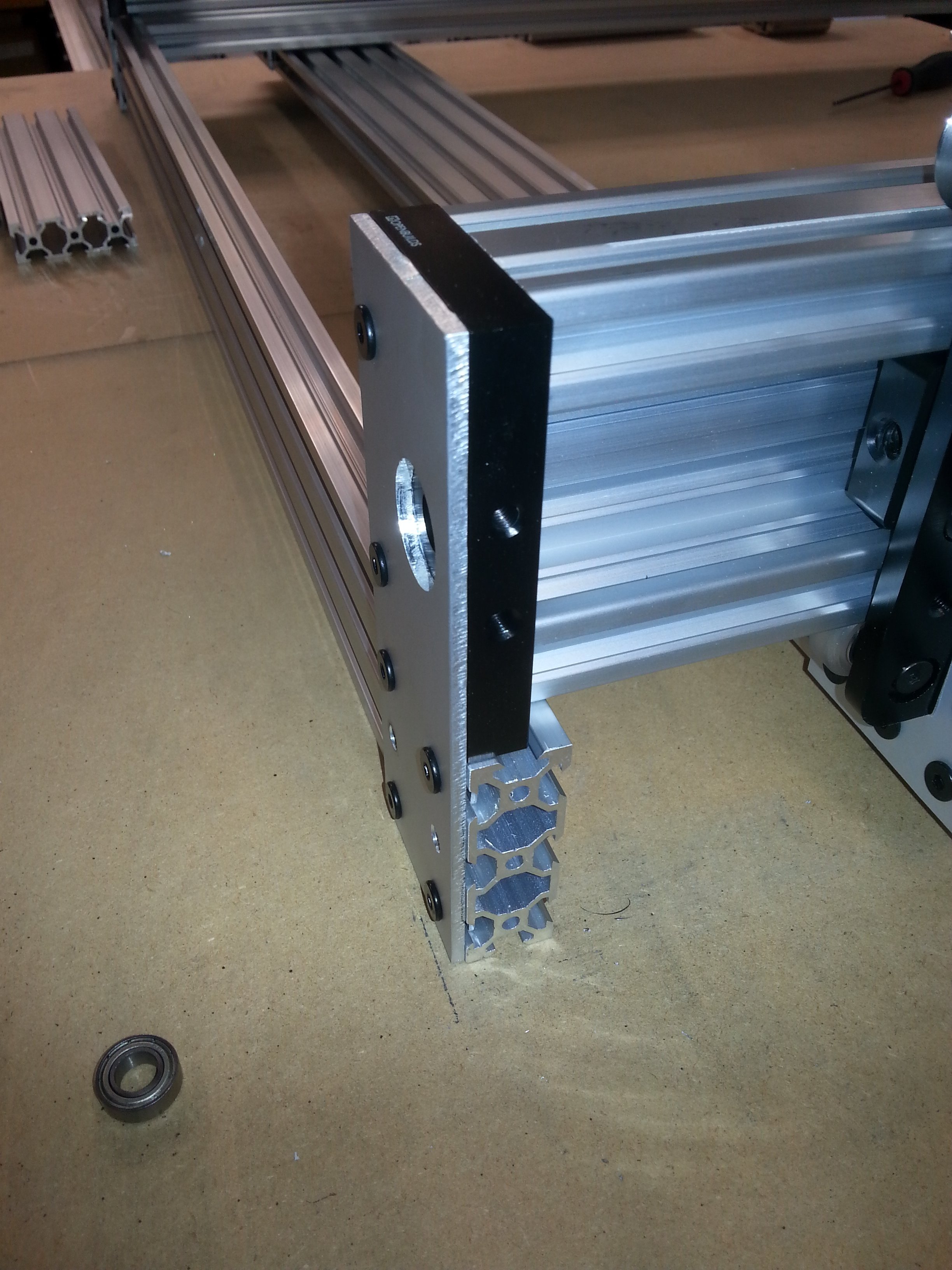
A custom 1/8"plate bolts on the the ends of the X axis C-beam using holes on the end plates, and also attaches to the face of the 20x80 upright. This allows for maximum travel on the X axis. A photo of the gantry side is shown below, with the c-beam mounting plates and the 20x80 uprights shown. You can also see the 20x80 cross member that connects the bottom of the two gantry plates. This piece really stiffens the gantry and keeps it square. There will eventually be another brace below the x-axis to beef up the gantry even more.
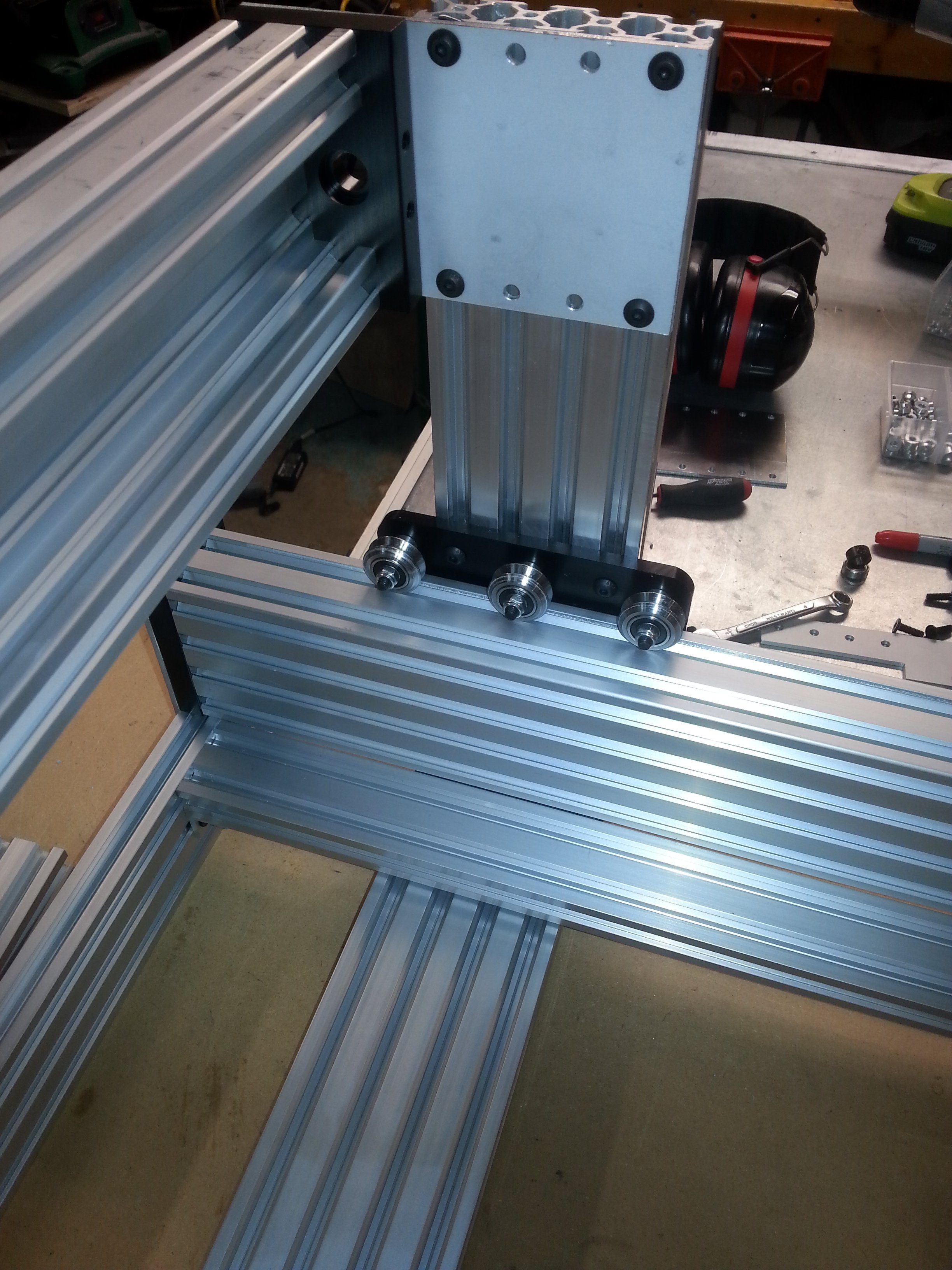
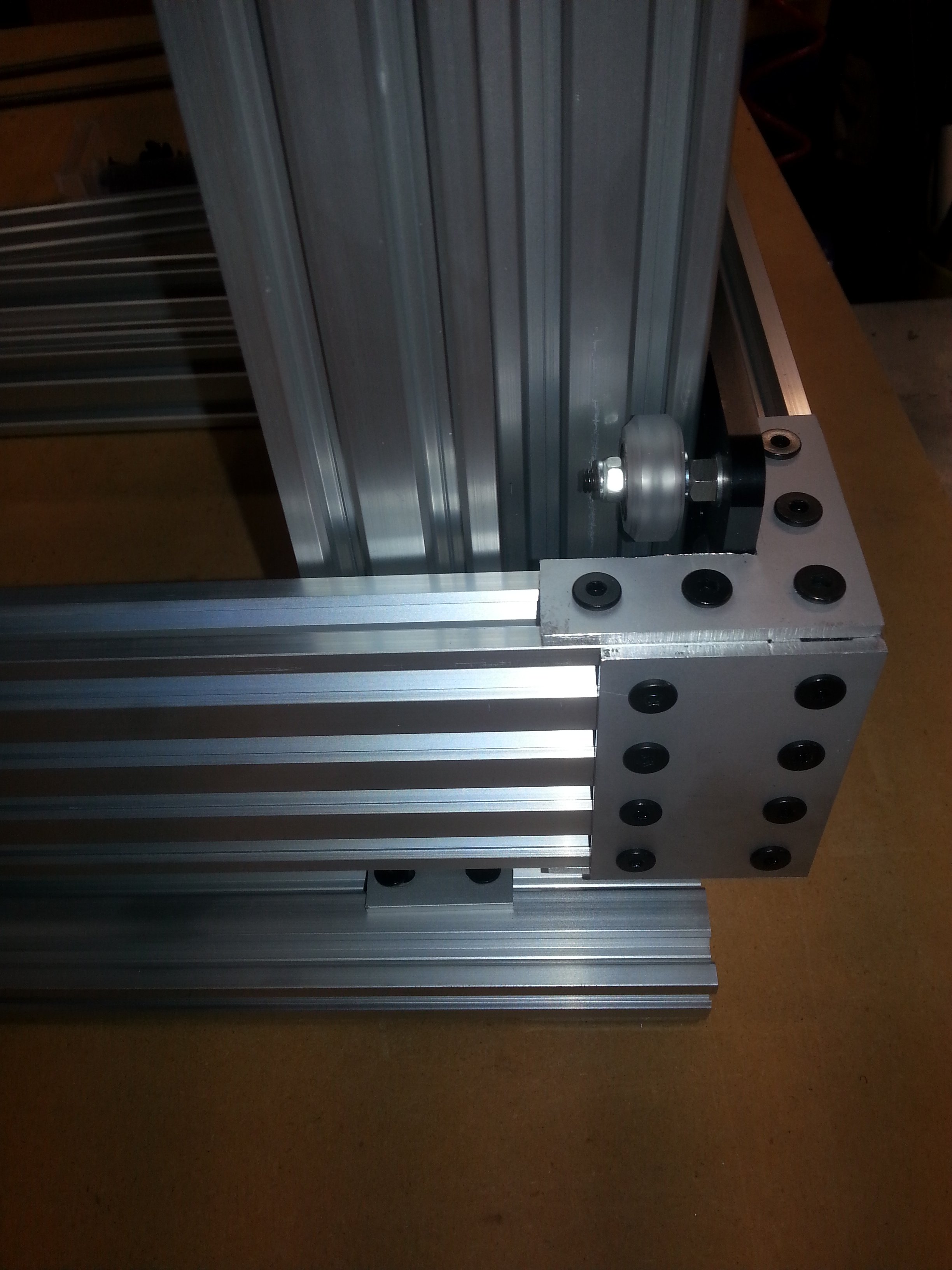
The bottom of the gantry is shown in more detail below. More custom made brackets turned out on my C-Beam Machine are used here. One bonus is that the bottom 20x80 piece is exactly the same length as the x-axis c-beam with its mounting plates, so it's easy to size. The uprights are tapped on the bottom for the 8 hole plates, and these plates use t-nuts on the horizontal piece, so there is a bit of width adjustment of you need it. The Angle brackets stiffening the corners are also custom pieces. The gantry plate actually rests right on top of the horizontal 20x80, helping to keep it square. There is just enough clearance for the center wheel.
The base mounting plates are shown in the next photo. They are custom pieces off the CBM as well. They bolt onto the tapped holes on the c-beam end caps, and bolt onto the 20x60mm foot with t-nuts. This allows a bit of side-side adjustment to align the c-beams. The back foot is exactly the same, only the stepper motors bolt onto the two top holes and hold the plate in place as well. There will eventually be 4 inner pieces running between the front leg and the back leg, which will support the spoil board. 2 will be 20x40's at each side, and two more spaced evenly in the center will be 20x60's. I used wider pieces because they have to lay flat with the wide face horizontal, in order to clear the moving gantry connector, so the inside ones are wider to be stiffer. They will be bolted to the spoil board from the top to stiffen the whole table.
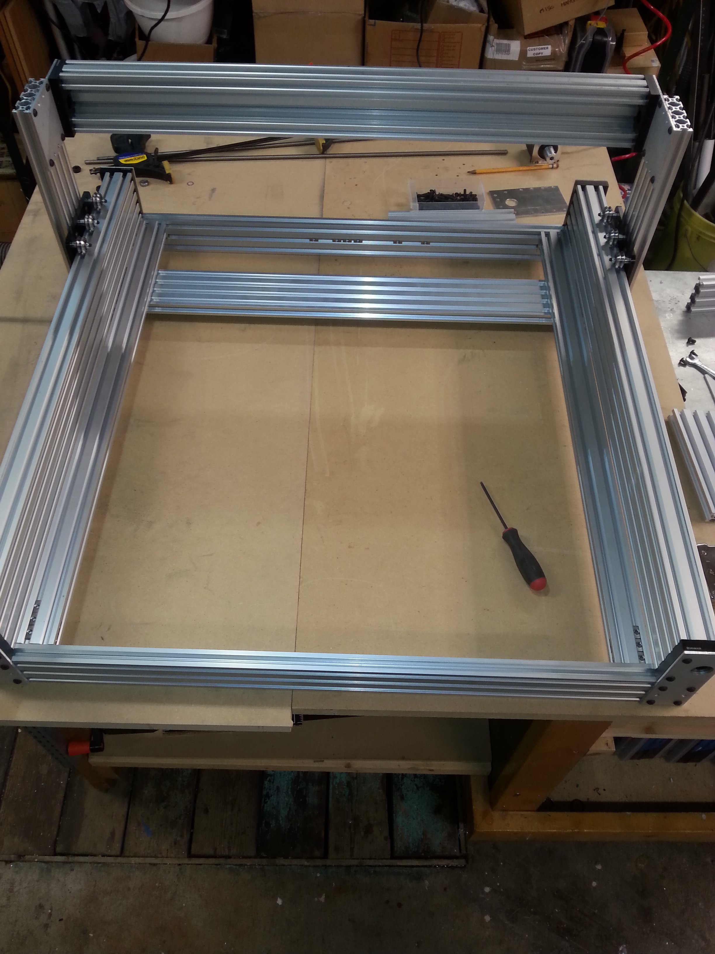
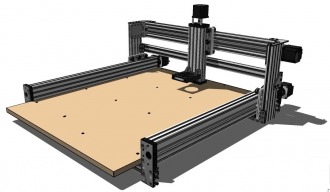
This is kind of a top view of the assembly so far. I have the outer 2 20x40's table supports in place, still have the inner 20x60's to put in yet. I have the leadscrews cut and ready to install for the y axes, I will have to order another leadscrew for the X axis. I will work on it more this week, and keep posting as I go. I need a few more parts to finish up, so it will be a week or two before it's done.
Metalguru's C-Beam 750
Build in 'Cartesian Style CNC' published by Metalguru, Jul 12, 2016.
This is a C-Beam build, fairly heavy duty, and 750mm x 750mm. Should be a good, sturdy machine that's relatively easy to assemble.
-
-
Build Author Metalguru, Find all builds by Metalguru
-
- Loading...
-
Build Details
- Build License:
-
- CC - Attribution NonCommercial - CC BY NC