
I finally got some time to rebuild my c-beam machine recently. This build is yet another modification to a standard C-Beam Machine kit to make it more useful and more stable. It uses a minimum of additional parts, recycling all the original C-Beam Machine parts and just adding 2 linear rails, a stock c-beam gantry plate and wheels, 3 pieces of 20x40 v-slot, and a bunch of hardware and brackets.
I changed the configuration around a bit, and added 2 linear rails to support a larger table. I had ordered the rails some time back from China, with the intent of doing this mod to my machine. The rails are 12mm x 700mm fully supported linear rails. They cost something like $70 for the pair from Ebay.
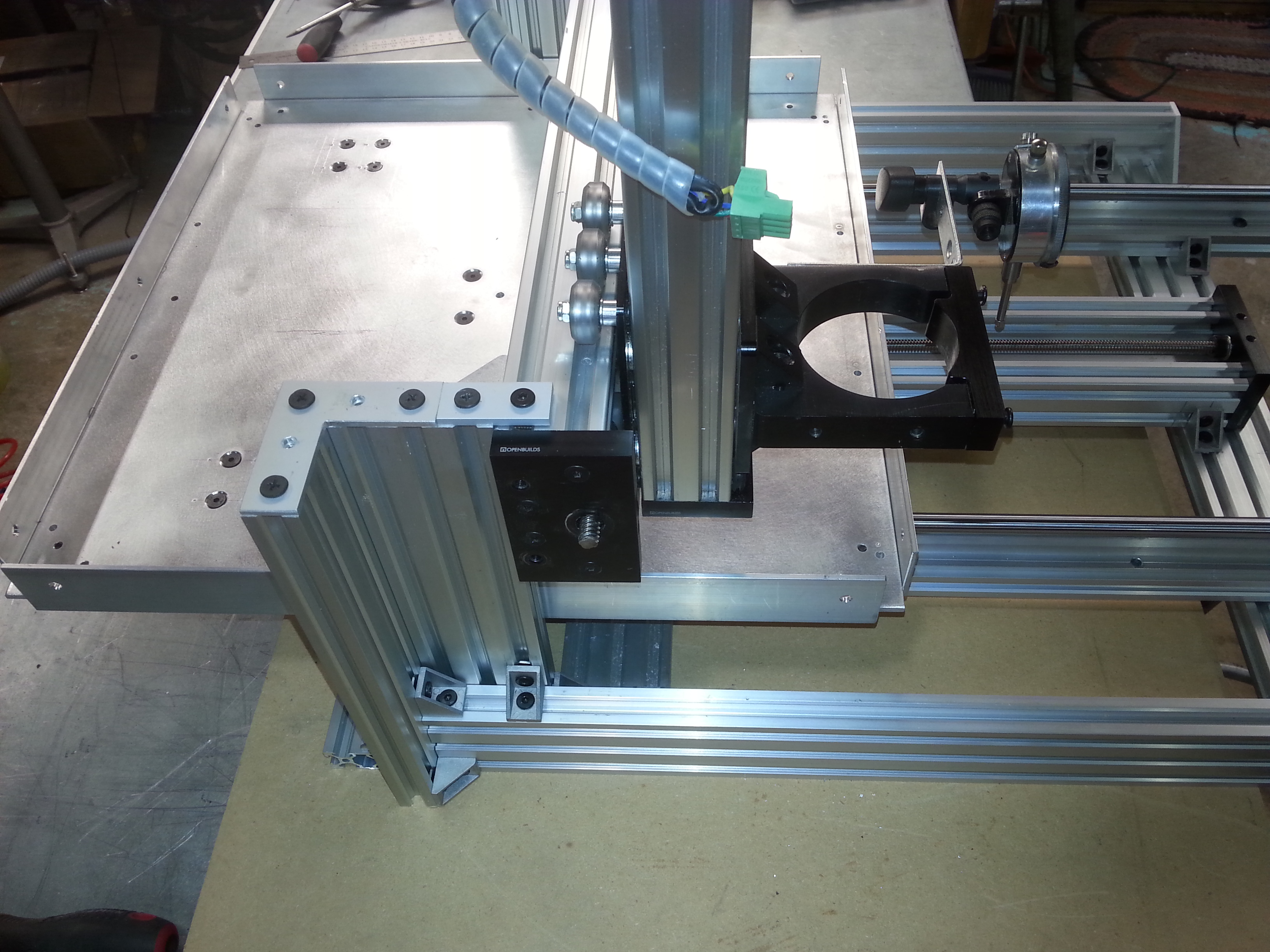
I started by flipping the l-shaped support columns around so that the L was behind and outside the stock side rails. This gave me about 80mm more space in between the rails for a larger table. Several cast corner brackets anchor everything together. This also allows the X-Axis c-beam to be mounted to the rails at the very ends, using corner brackets underneath and behind to anchor it to the vertical rails. This extends the x-axis travel by at least 40mm, and eliminates that dang corner bracket that dings up your wheels when you hit the end of the axis travel. The x-axis c-beam now has pretty much maximum allowable travel of 500mm minus the width of the wheel plate, ending up with about 410mm of travel.
The next step was adding the linear rails. After doing a SketchUp model, I figured I needed about 700mm of linear rail to get a decent spacing between the linear bearings, and to get the full 420 or so mm of Y axis travel. I planned on using a 1/4" aluminum plate table, so I had to raise everything up a bit to clear the stepper motor in the back. I originally wanted to flip the Y axis c-beam over so it wouldn't fill up with cuttings, but I realized it would have meant redesigning the whole frame to do it, so I didn't bother. The larger table keeps the c-beam covered most of the time anyway, so should keep out most of the junk.
I determined that the linear rails would have to be raised up about 20mm, so I just cut a piece of 20x40mm v-slot to fit under each one. The holes in the linear rails just about lined up with the slots in the v-slot, I had to drill out the mounting holes on the rails to about 5.6mm to get it to fit. I mounted the v-slot to the existing rails with cast corner brackets, and added another cross piece made of 20x40 v-slot at the back of the machine to support the back end of the rails better.
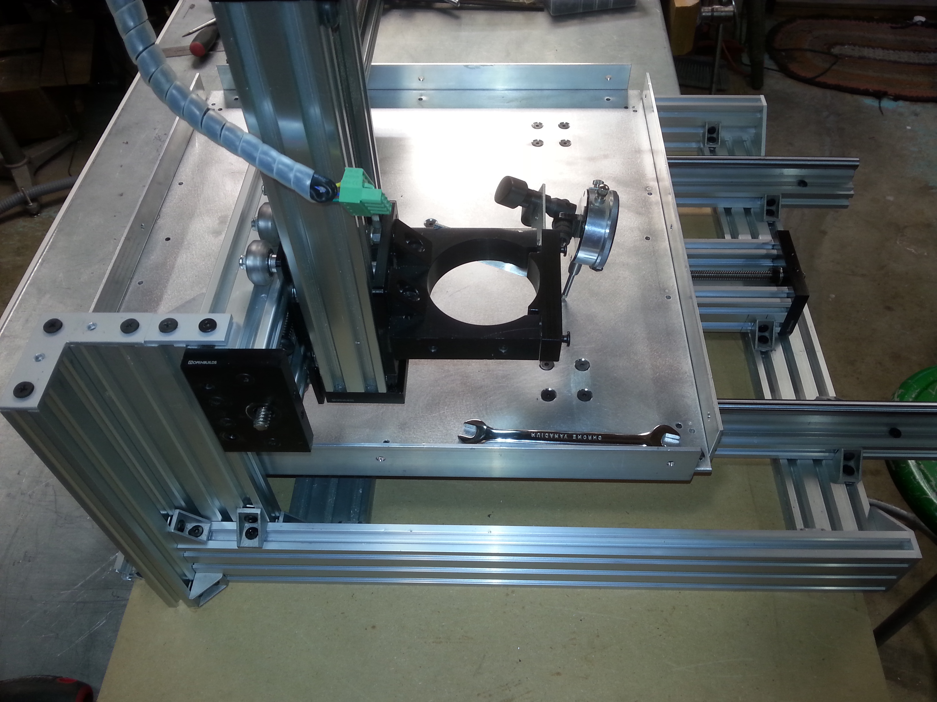
I used the stock C-Beam for the Y-axis drive, but took off the universal build plate because it limited the Y travel too much. I replaced it with a standard 75mm x 75mm C-beam gantry plate with mini v-wheels. It only has to support the center of the table and transfer the drive, so it does not need much strength.
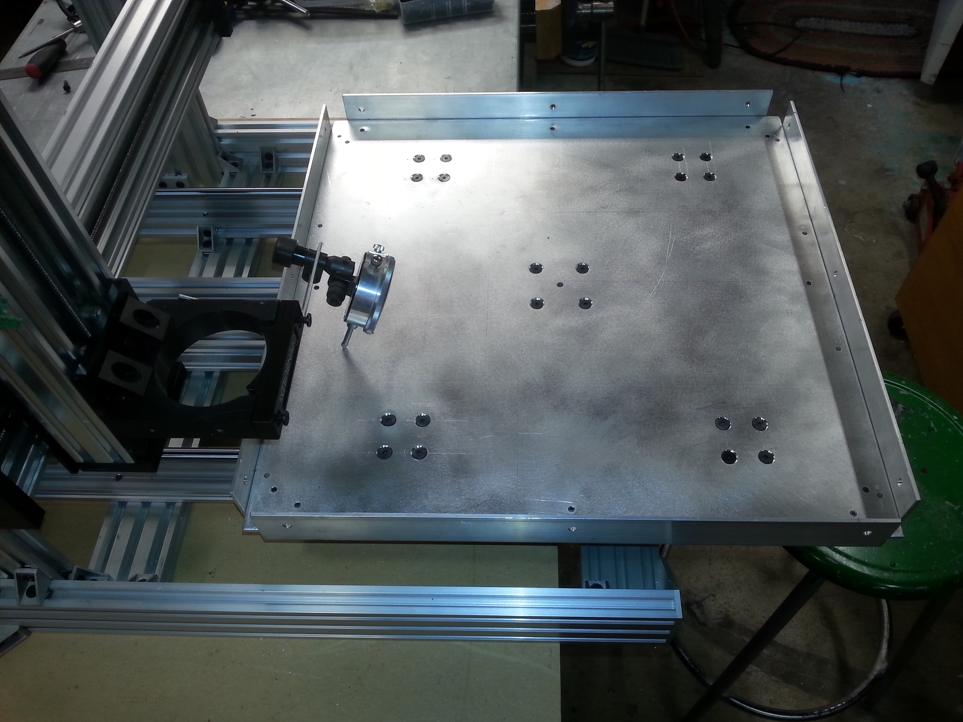
Now to build the table. I cut the plate about 450mm square, which fit nicely between the frame rails with a bit of clearance. I measured and drilled it for the linear bearings, and the c-beam gantry mounts using four of the pre-tapped holes. I ordered some 13mm OD x 5mm hole spacers from McMaster Carr after determining that I needed 20mm height on the C-Beam gantry plate, and 8mm height on each of the bearings. I also ordered flat head screws of corresponding length for all of the spacers. All of the screw holes going through the table are countersunk so the screw heads sit well below the surface.
Just a note about the table - when I went to install the aluminum angle on the table, I realized that the inside corner of the angle had a radius, and the angle would not fit snugly against the 1/4" plate. So, I went over to the router table, installed a 1/4" radius carbide bit, and proceeded to use it to put a radius on the bottom side of the plate. It worked amazingly well, the carbide router bit effortlessly cut the radius on the plate, and the angle now fit snugly up against the plate with no gaps. I had never thought to machine aluminum on my router table before, but it worked great, cutting foil thin chips of aluminum that went flying around the shop.
I installed the table, centered it, and checked that all was working properly. It took a bit of doing to get everything centered and aligned with no binding, but it works great. After checking the table for flatness, and aligning the x-axis to make sure it was parallel to the plate, I had less than +/- 0.1mm variation across the whole plate side to side and front to back. I was happy with this, but I added some aluminum angle sides to the table both to keep it flatter, and provide support for a spoil board.
So, my final machining area is just a hair under 420mm x 420mm, which is well over twice the machining area of the original c-beam machine. The table is rock solid, moving less than .001" when a 25lb weight is place anywhere on it. I am more than happy with this enhancement, and for under $200 in parts it was a very worthwhile investment.
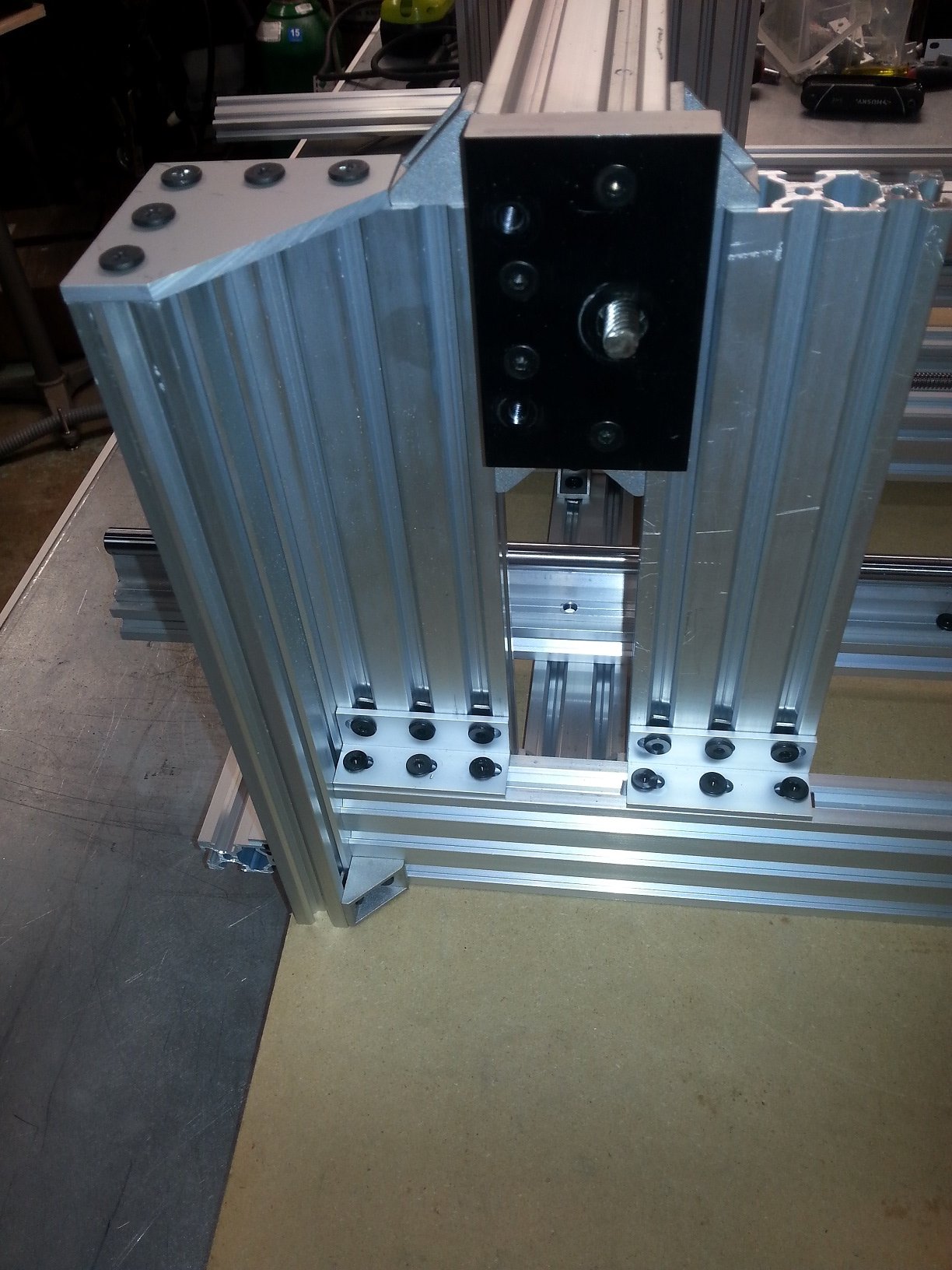
This is the back side of the machine. Note reversed support posts, and c-beam x axis mounting

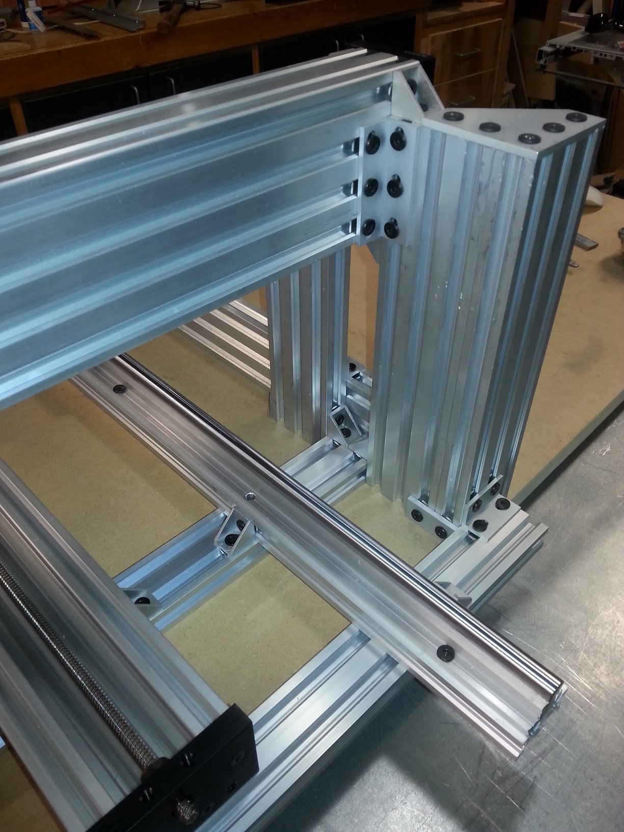
This is a side view showing more detail on the posts and rails
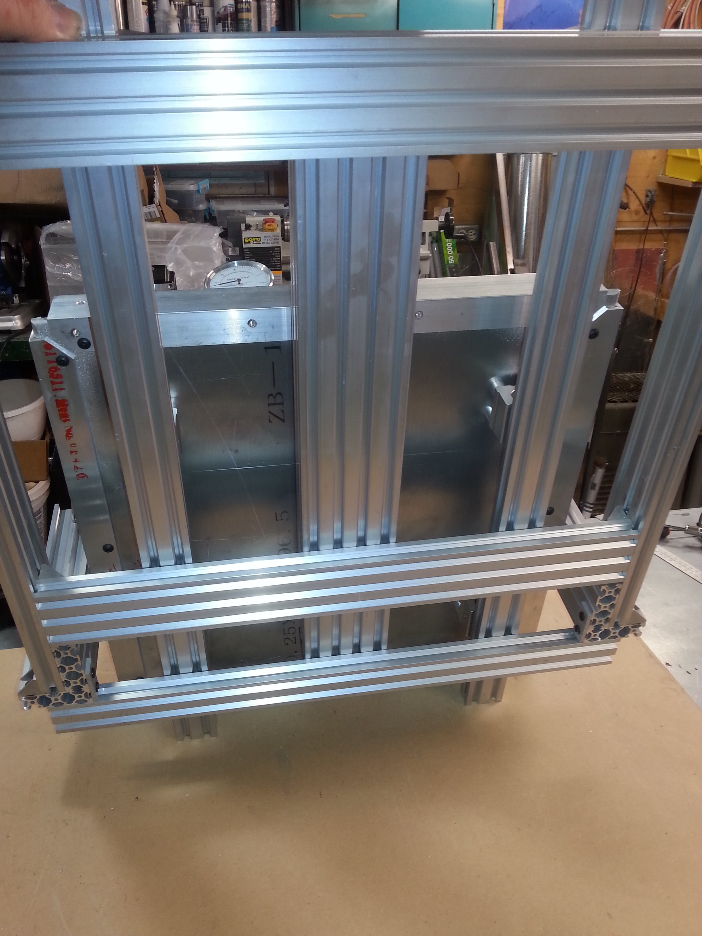
This is a bottom view
This is a view with the table fully forward...
and fully back...
Now I just have to mount the electronics back on the machine and get her fired up!
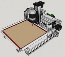
By the way, I have designed a compact electronics mounting plate that puts everything neatly onto a 500mm long plate that mounts on the back of a c-beam, or nicely on an OX as well. Here is a couple of renderings from SketchUp:
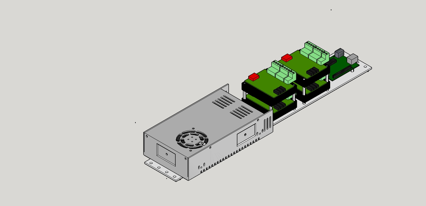
I use a screw terminal shield on the arduino (not shown) to make wiring easier. I also use separate stepper driver modules with their own heatsinks that I buy off Amazon or Ebay. Makes wiring easy.

UPDATE:
I was thinking about how to upgrade the X and Z axis rigidity after doing all the table mods. Then, I saw Ronald's post on upgrading his machine, (Upgrading the “old” C-Beam machine) I decided to take this to the next level. Creeping Featuritis is starting to set in...
I am going to order the double wide C-Beam gantry plate and upgrade the Z Axis to the stiffer 8 mini v-wheel wheel configuration. I also want to add the belt drive stepper motor reduction but the parts are no longer in the parts store. Hopefully, they are just temporarily out of stock. (See My Solution to Belt Reduction Issues for information on how I set up the belt drive)
I am also going to upgrade the X-Axis to the 12 wheel configuration by adding another small v-slot gantry plate on the back of the x axis c-beam and doubling up on all the wheel assemblies. This should give me quite a bit more rigidity without changing over to the Xtra Large gantry plates, which would be stiffer, but also reduce my X axis travel by about 85mm. As it is, even with the small v-slot gantry plate added to the back side of the axis, I will lose about 40mm of travel, since the rear plate will hit the cast corner brackets that mount the back of the c-beam well before the plates hit in the front. No way around this for now, and the extra rigidity will make up for the lost travel.
I may even double up on the small v-slot gantry plate on the front side of the X axis, just put two of them back to back on the front side. They will both bolt to the back of the z-axis c-beam, and have the wheel mounting bolts go through both plates. This should stiffen it up even more, but I'm not sure if the difference will be noticeable
I have posted the updated SketchUp model if anyone is interested..
UPDATE 2
Well, some more work on the design. Waiting around for parts to arrive, so I thought I would do a bit more stiffening on the X Axis side of things. I noticed that the X axis C-Beam could be moved by reefing on it, and I thought "That's not good..." So, this is the result. I should stop thinking. It costs me money every time...
I started by removing the 20x60 cross member on the bottom of the frame and replacing it with a 20x40. This is the same width as the c-beam, so it gave me the ability to add another 20x6o upright to support the front of the X - axis C-beam. I raised the c-beam up by 20mm to give a bit more clearance to the table, and this allowed me to add corner brackets at the top of the uprights to hold the C-beam.
I also replaced all the cast corner brackets on the uprights with a couple of 6-hole corner brackets. Makes things a bit neater.
The next step was to add some cast corner brackets under the c-beam to support it a bit better, and a couple more 6 hole corner brackets on the back of the c-beam to stiffen it even further. I also added a few cast corner brackets to support the bottom of the uprights as well.
I should be able to add another 3mm spacer between the back wheels and the back plate so that the plate clears the corner brackets. Couldn't do that with cast corner brackets. This allows me to maintain maximum travel in the x-axis. Adding the two front support beams and the back wheel plate with the 12 wheels has already lost me about 40mm of travel, which I can live with.
Finally, I put the whole thing back together. It's definitely going to be a PITA to get the X/Z Carriage back on the c-beam. That's one of the things I don't like about the X axis design, is that you can't get at the wheel bolts on the front side of the plate to tighten them. I just jerk the wrench and hope I can get them tight. Also, you can't adjust or remove the Z axis without taking the whole dang thing apart. The only good thing is that the carriage is almost as narrow as the Z axis c-beam, so you get maximum axis travel. Eventually, I will design some X-shaped plates that will clear everything but give a wider wheel stance, and put bolt head clearance so you can bolt the x and z axis plates together, something like the new X-Large C-Beam Plates.
Oh, one more PITA, I discovered that I can't get at the setscrew for the bearing lock collar. Had to drill a hole down from the top of the c-beam and put in a shorter end cap screw so I can put the Allen key down through the hole to tighten the lock collar.
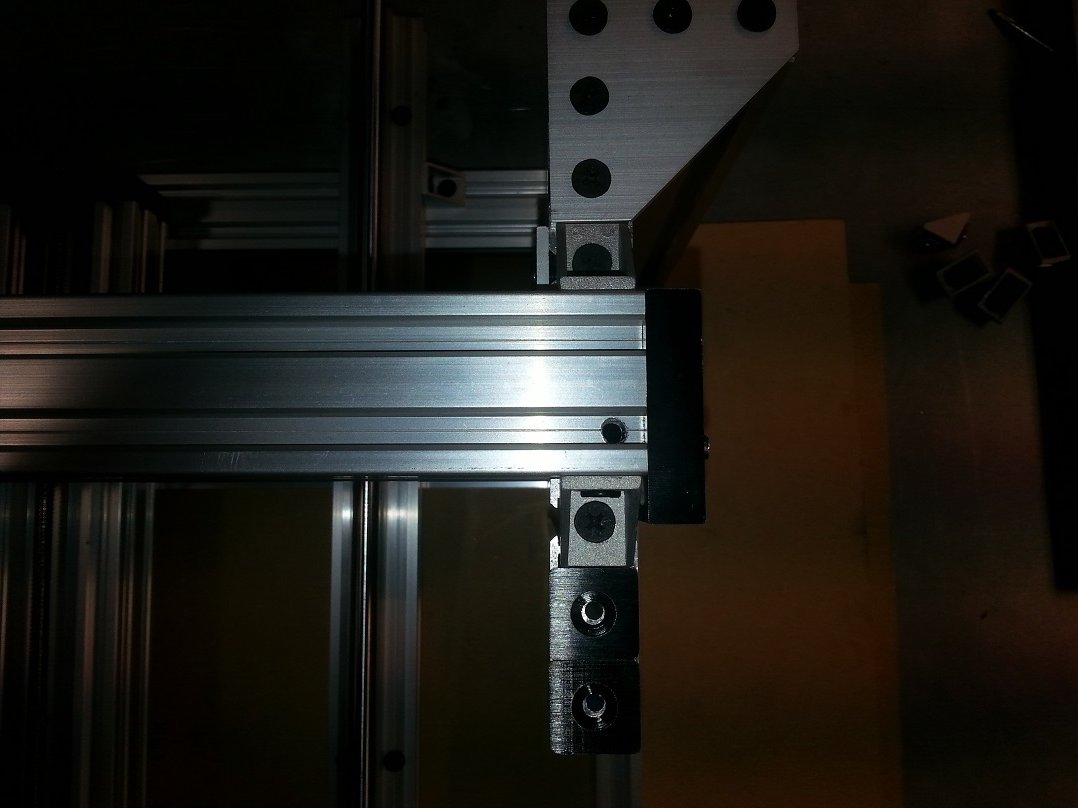
That last photo was a bit dark for some reason. Anyway, you can see the hole on the right side of the c-beam.
So, after playing with this a bit, the x-axis c-beam is now rock solid. I can put my considerable weight on it and I can't feel it move a bit. The whole axis is amazingly sturdy now.
Now all I have to do is wait for my belt reduction and extra wheel plates to arrive so I can beef up the Z axis. I also need a double c-beam gantry plate, but that will have to wait for my next major order at the Parts Store.
I'll keep everyone posted as the build progresses. BTW, I haven't updated the sketchup model yet. I'll do that in the next few days.
UPDATE 3:
It's pretty much done. All reassembled and ready to go, with the exception of the double wide C-Beam Gantry plate. That should be in my hot little hands middle of next week. I think it looks good.
Thank you so much Ronald van Arkel for your inspiration. I hadn't quite decided how to proceed until I read your posts. I didn't quite do things the same way, but that's the beauty of the Open Community. "I did it MY WAY". Thanks to all the others who contributed either directly by commenting or indirectly by posting something somewhere that tweaked my brain.
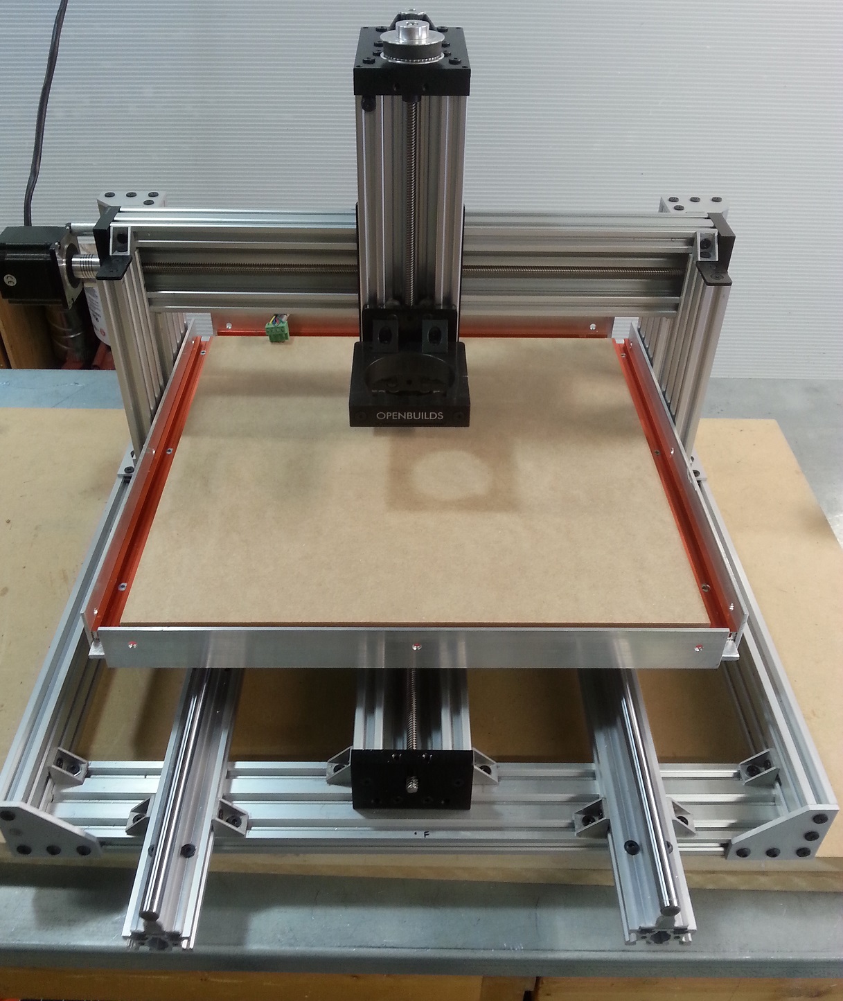
Full Frontal Nudity! Note I added a spoil board and 4 t-slot tracks around the perimeter of the table for work hold down. No, the gaps in the corners are not a mistake, they are there so I can slide 1/4" bolts into the t-track.
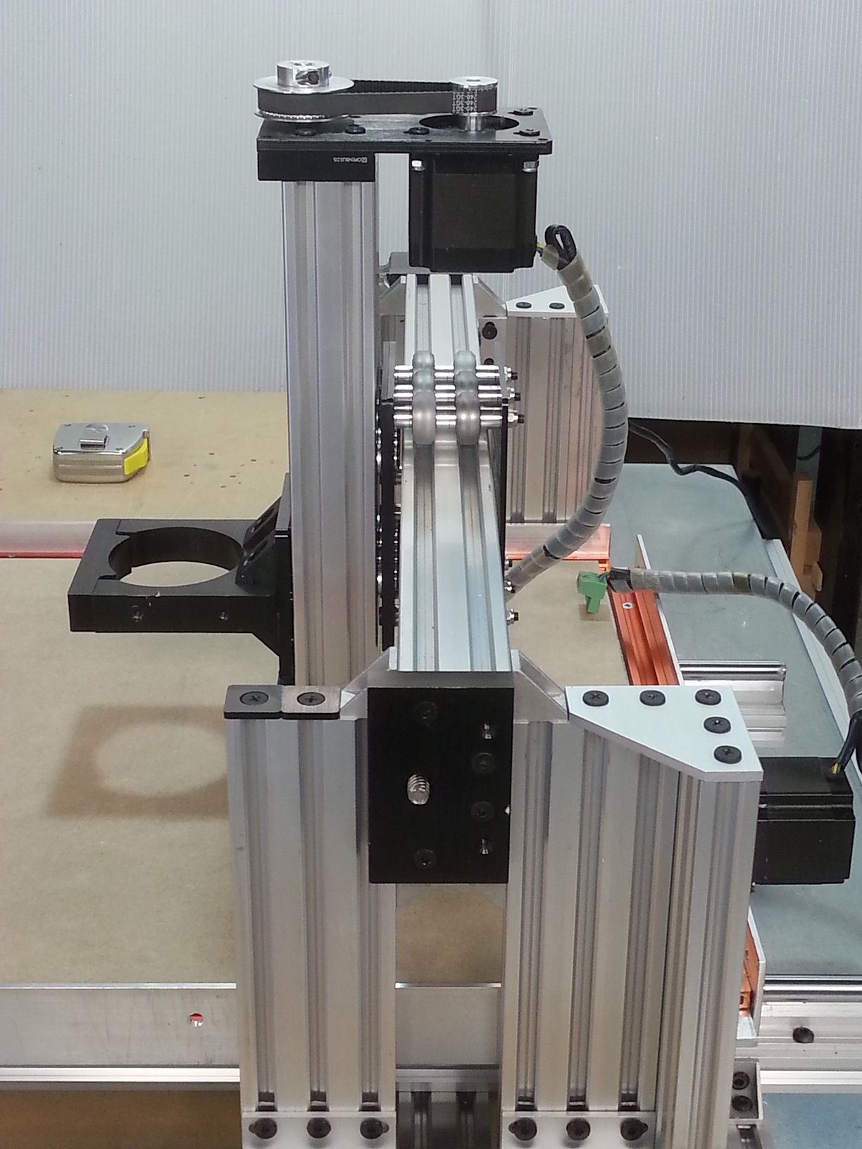
Side view of X carriage and Z axis. Note the double 20-60 build plates on the front side of the carriage, and the single on the back. I figured doubling them up would be stronger. You can sort of see the extra 1/8" spacer I put behind all the wheels on the back side to space the back build plate out enough to clear the angle bracket on the back of the c-beam. This way I didn't lose any X travel, as the carriage goes right over until the plate hits the uprights. Don't have the electronics mounted yet... Might put a drag chain on for the Z axis, haven't decided yet.

Back view. The carriage goes right to both sides, giving me almost 400mm of travel on the X axis. Y axis travel is about 425mm. Love the belt drive on the Z axis. Hopefully it works as good as it looks. See My Solution to Belt Reduction Issues for how I modified it.
Creeping Featuritis has been cured for now, with a shot of hardware and an injection of time. I'm sure I'll find something else to "fix" at some point. But, now to make some plates and see how it all works together.
C-Beam Machine Too
Build in 'X/Y Table Style CNC Mill' published by Metalguru, Jul 15, 2016.
C-Beam Machine upgrade using linear rails to increase machining size by 2.5 times and increase rigidity
-
-
Build Author Metalguru, Find all builds by Metalguru
-
- Loading...
-
Build Details
- Build License:
-
- CC - Attribution - CC BY
Reason for this Build
To improve the C-Beam machine design at minimum cost.Inspired by
-
Attached Files: